The Precision Motion Bottleneck in Modern Motion Control
In high-end semiconductor lithography, wafer inspection, 5G chip testing, and ultra-precision CNC systems, linear direct-drive motors serve as the core engine powering high-speed, sub-micron positioning. Conceptually, a linear motor is an "unrolled" rotary motor. However, this flattening fundamentally alters the magnetic flux distribution, mechanical stress profile, and thermal dynamics of the lamination core.
As modern automation pushes for higher acceleration, denser thrust output, and near-zero position tracking errors, traditional iron core manufacturing techniques are reaching their physical limits.
High-Frequency Thermal Runaway
Rapid reciprocating motion induces massive eddy current losses, causing the mover core to overheat and deform.
Thrust Ripples & Cogging Force
Magnetic disalignment and structural discontinuities create severe force fluctuations, destroying tracking precision.
Vibration and Delamination
Traditional mechanical interlocking fails under ultra-high acceleration, leading to micro-vibrations, acoustic noise, and core distortion.
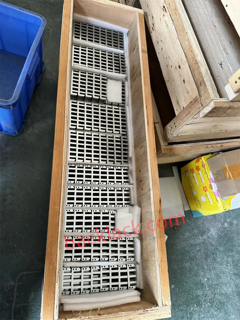
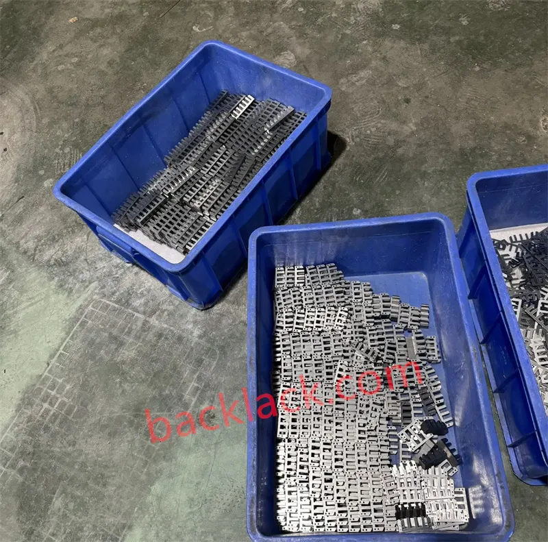
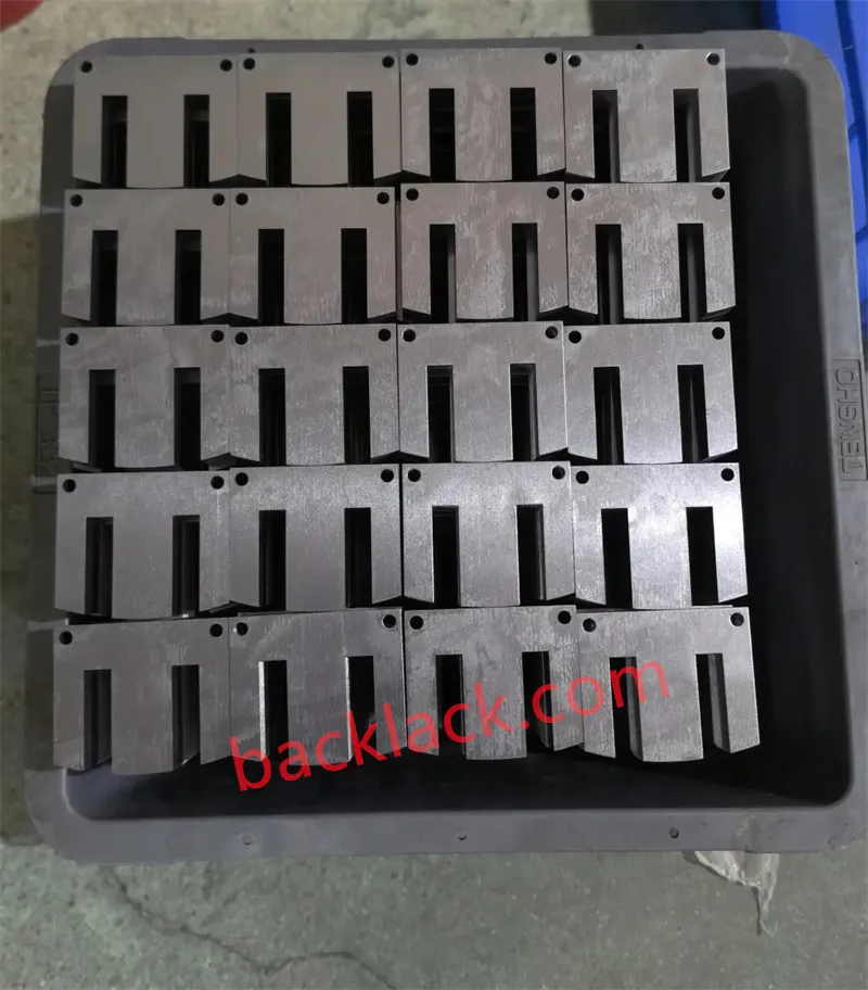
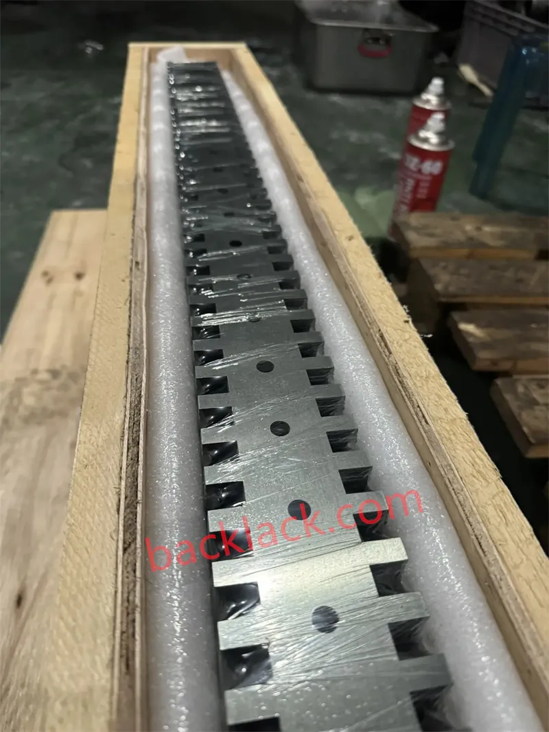
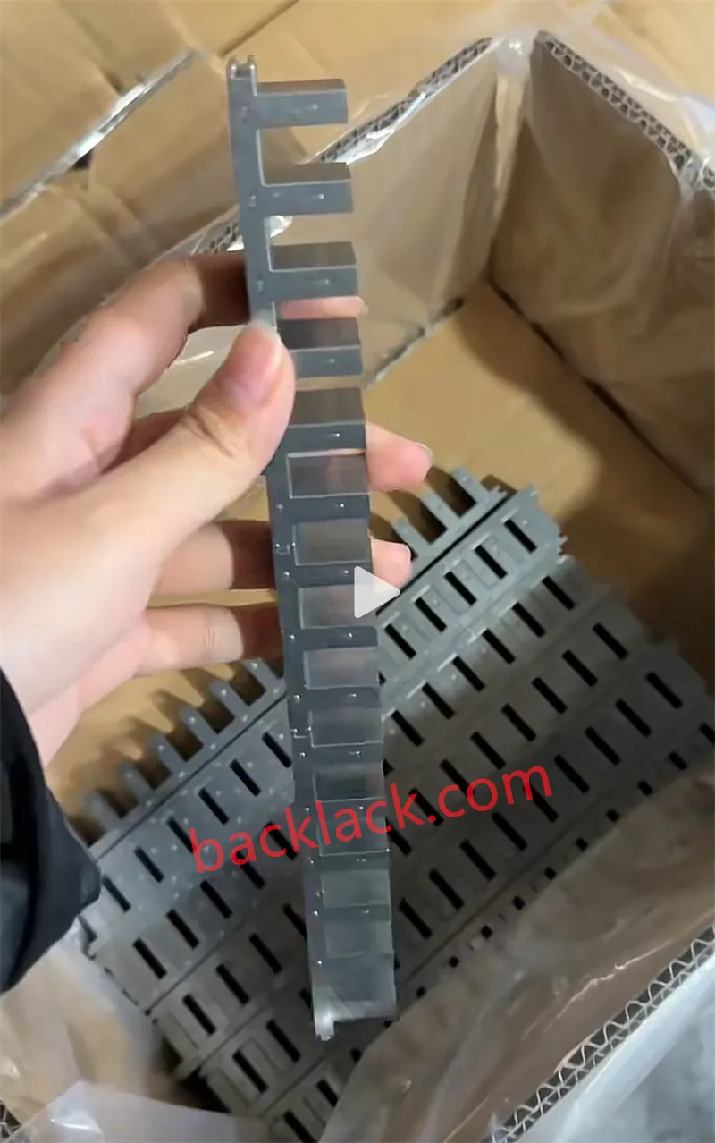
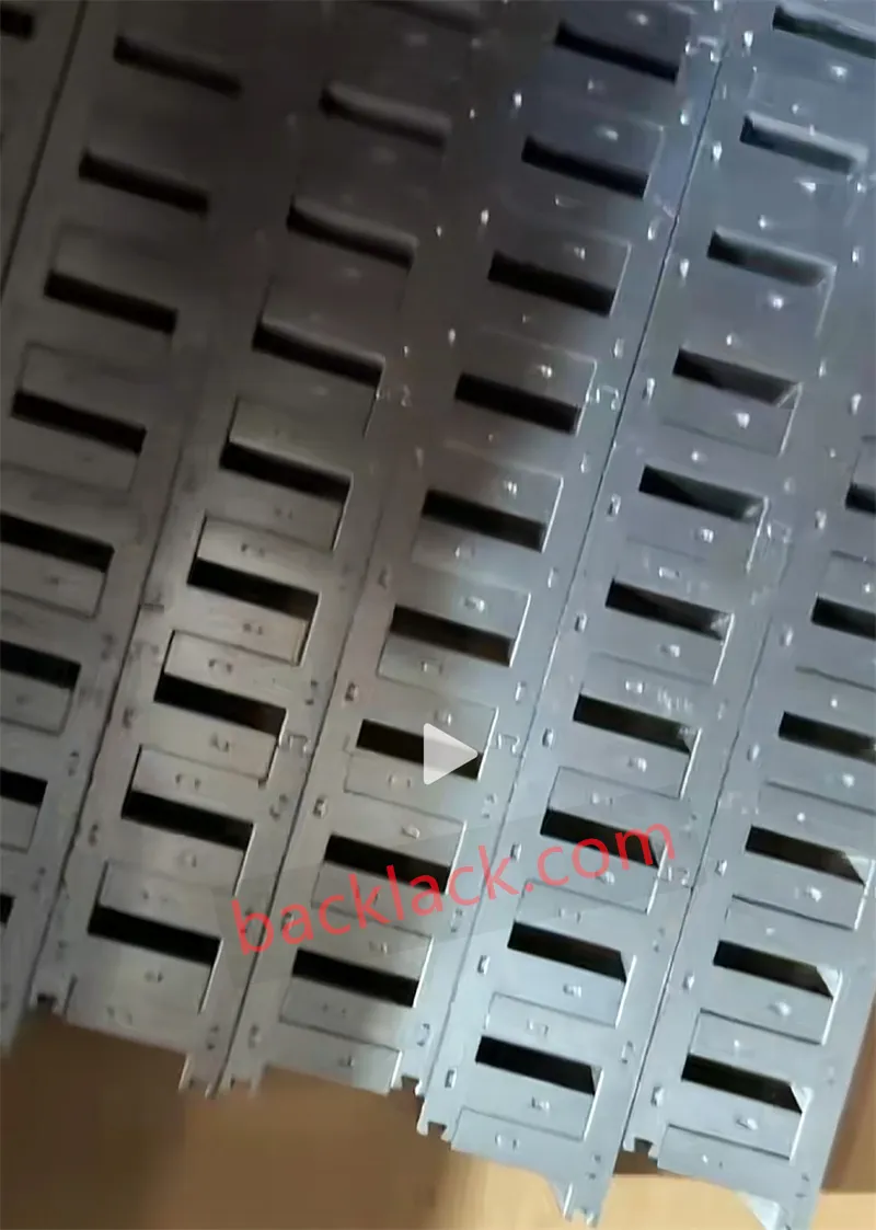
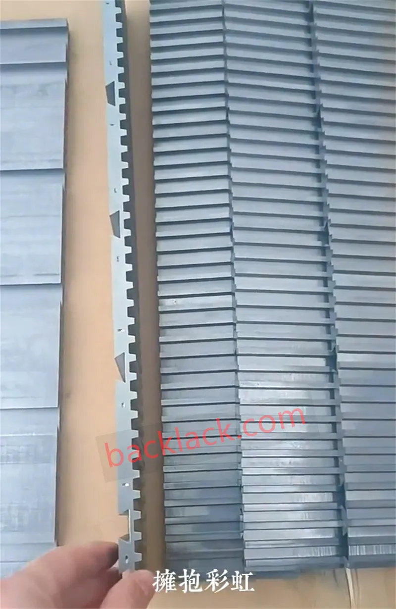
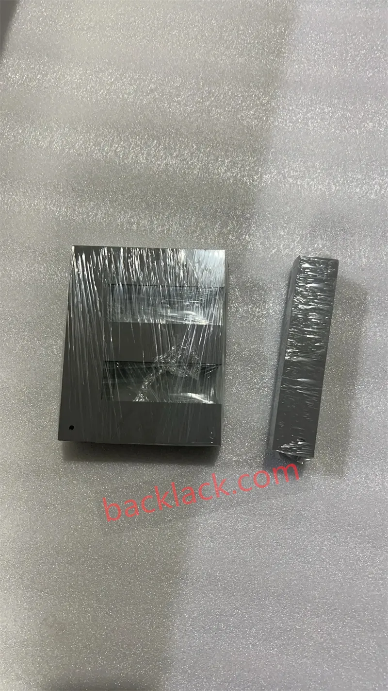
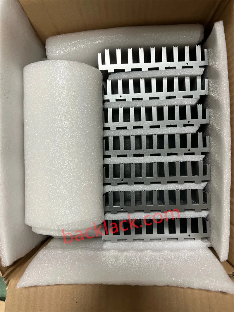
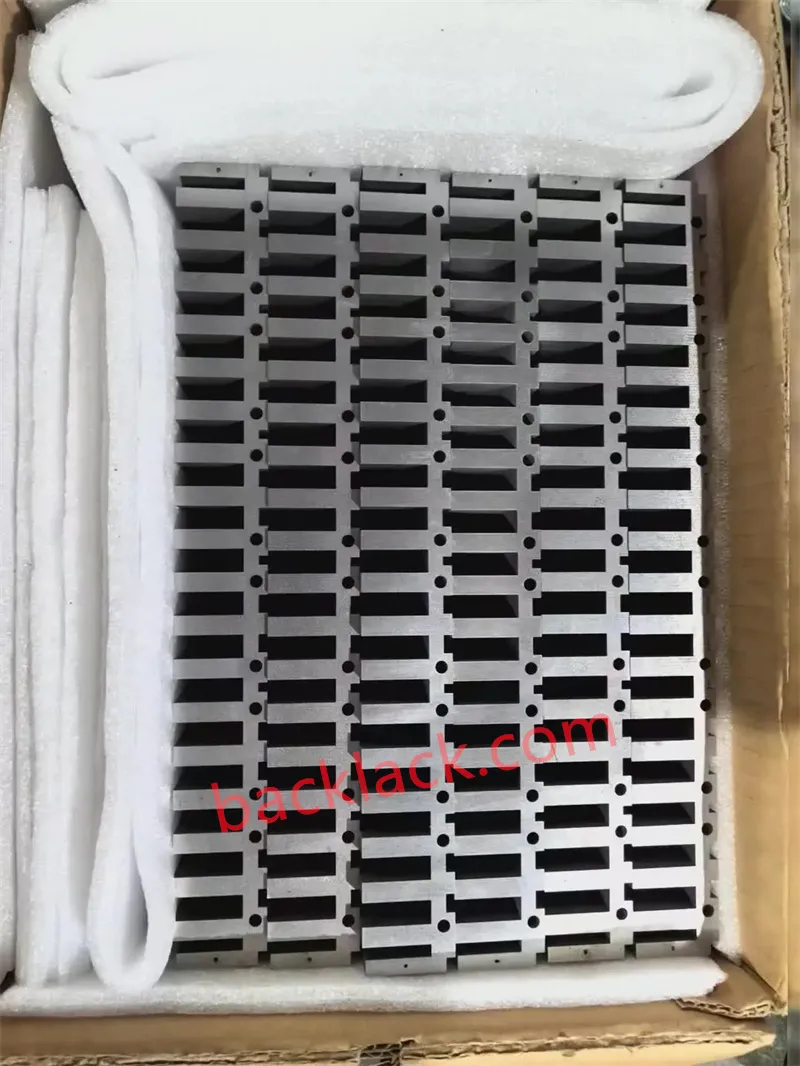
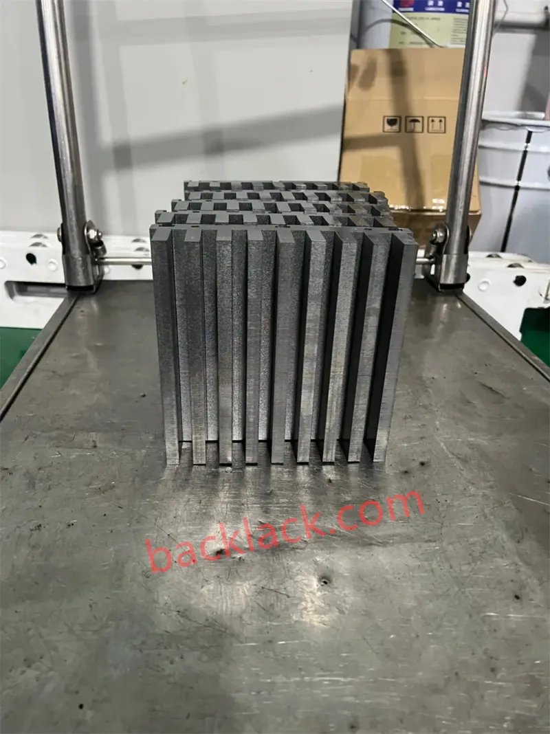
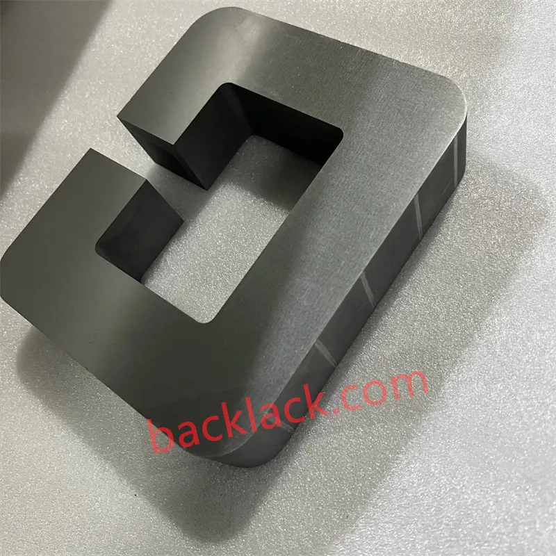
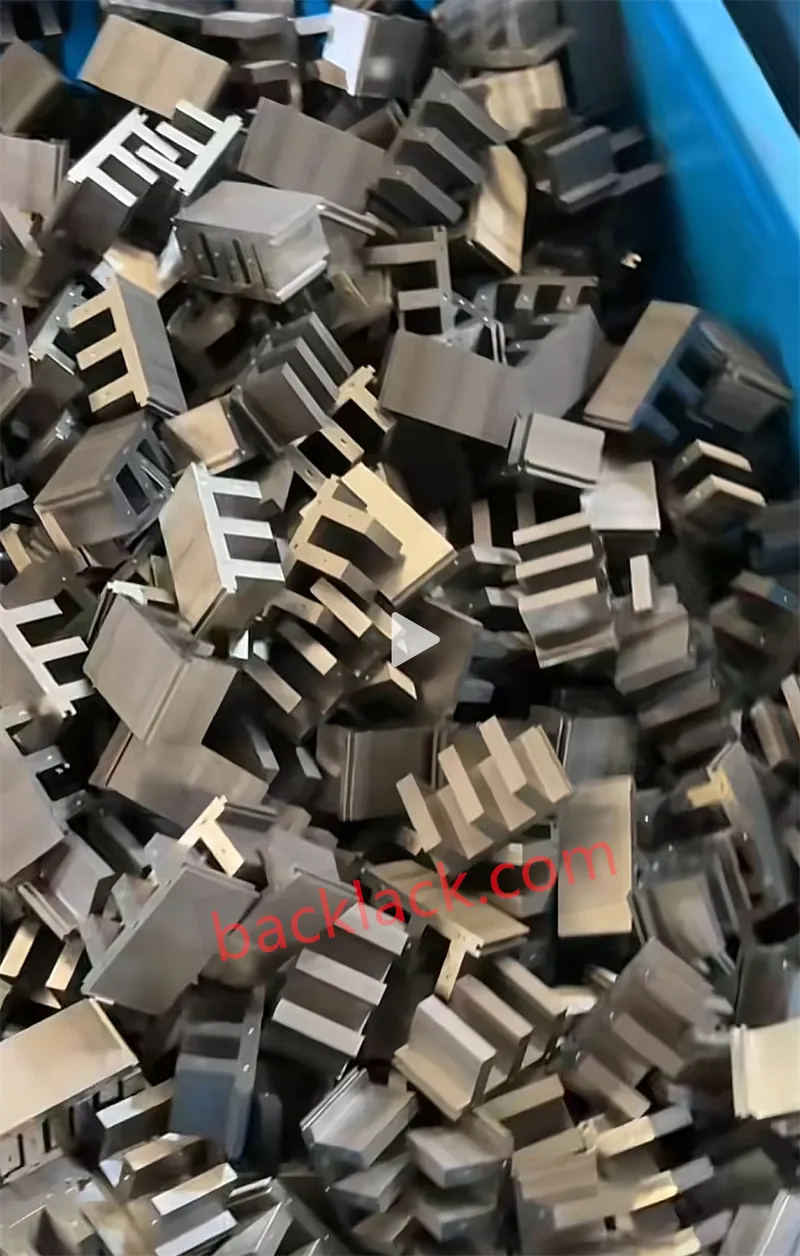
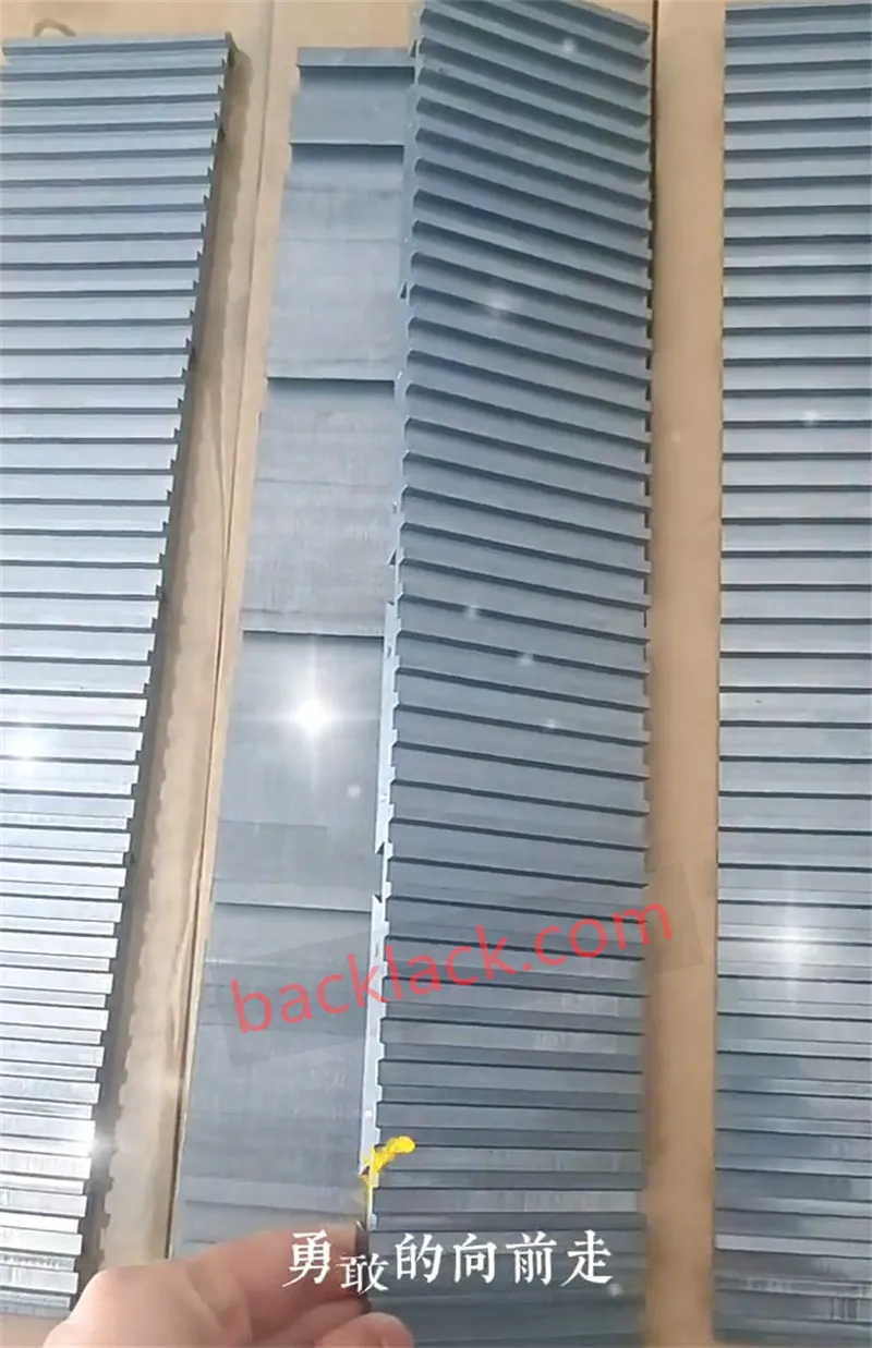
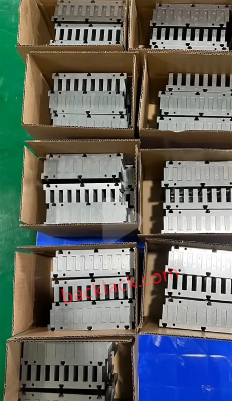
1. Material Science: Balancing Heavy Thrust Density with Low Core Loss
The primary advantage of iron-core linear motors lies in their high force density. However, selecting the wrong magnetic alloy rapidly triggers high-frequency thermal bottlenecks. Achieving an optimal balance requires tailored material selection:
| Electrical Steel Grade | Nominal Thickness | Saturation Induction ($B_{\text{sat}}$) | Core Loss Performance | Ideal Application Scenario |
|---|---|---|---|---|
| Thin Non-Grain Oriented (NGO) | 0.20mm – 0.35mm | ~1.70 T – 1.75 T | Moderate | Standard Industrial Automation & High-Speed Conveyors |
| Ultra-Thin Silicon Steel | 0.10mm – 0.15mm | ~1.65 T – 1.70 T | Extremely Low Eddy Current | High-Frequency, High-Acceleration Direct Drives |
| Cobalt-Iron Alloy (Hiperco 50 / 1J22) | 0.10mm – 0.20mm | 2.30 T – 2.40 T (+25%) | Optimized at High Induction | Semiconductor Lithography, Medical Robotics & Defense |
2. In-Mold Backlack Self-Bonding: Eliminating Interlocking and Weld Short Circuits
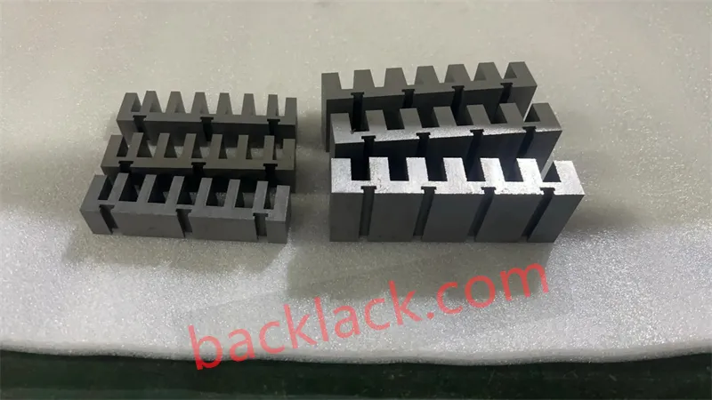
In traditional rotary motor cores, mechanical interlocking (riveting), cleats, or laser welding seams are common assembly methods. For precision linear motor stators and movers, these traditional techniques act as performance killers.
- Creates Inter-Lamination Short Circuits
- Spikes High-Frequency Eddy Currents & Core Heat
- Mechanical Thermal Stress Distorts Tooth Geometry
- Triggers Severe Cogging Force & Tracking Errors
- 100% Insulated Coating Film between Laminations
- Zero Inter-Lamination Short Circuits & Ultra-Low Loss
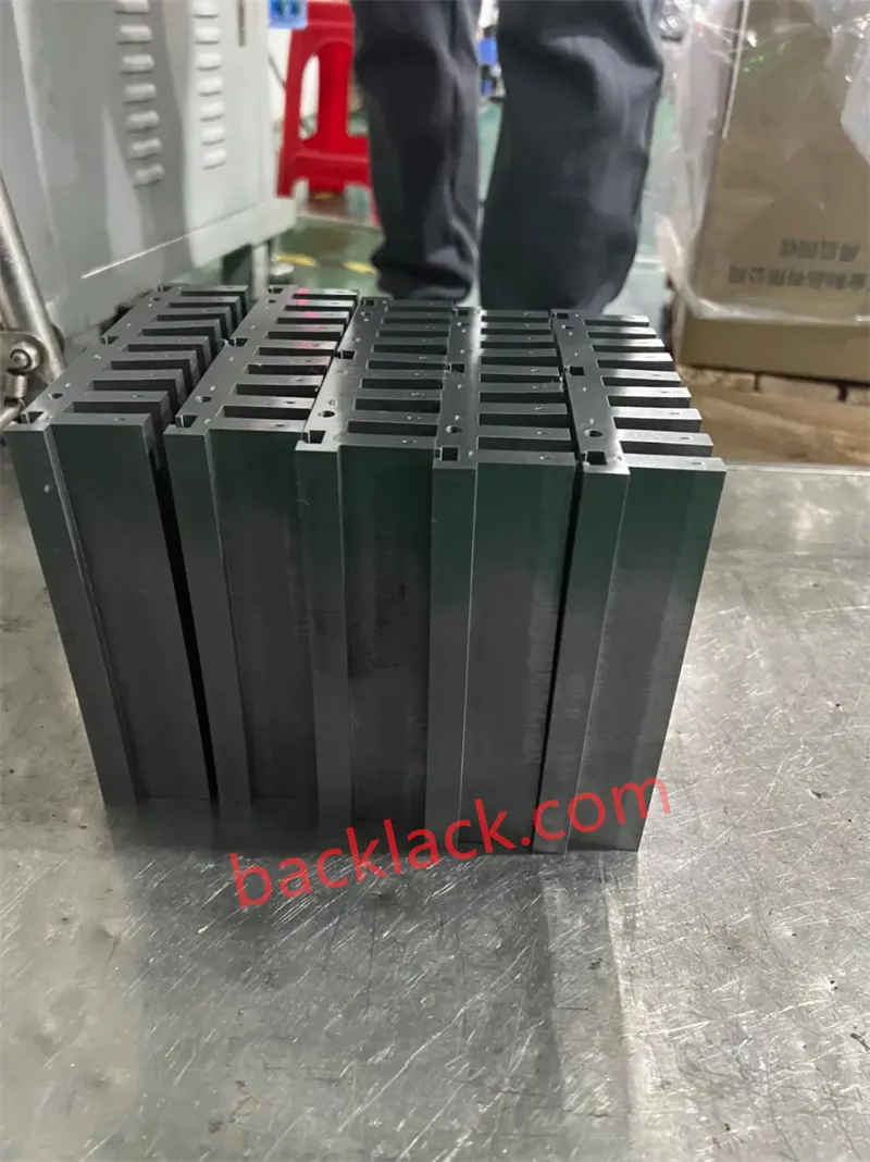
- Monolithic Structural Rigidity (Block-like Strength)
- Absorbs Reciprocating Impact with Zero Micro-Vibration
3. Suppressing Cogging Force & End-Effects at the Core Level
While iron-core linear motors deliver significantly higher thrust density than ironless designs, their open-ended magnetic structure introduces cogging forces and end effects, causing thrust ripples that ruin positioning accuracy.
Skewed Slot Stamping
By implementing progressive skewing during laser cutting or progressive die stamping, the slot edges are offset by a precise micro-angle. This breaks the periodic magnetic resistance cycle, flattening cogging forces.
Micron-Level Back-Side Precision Grinding
Linear motors maintain an air gap as tight as 0.5mm to 1.0mm. Any bow, tilt, or stack thickness variation triggers exponential magnetic attraction imbalances. Utilizing 3D CMM inspections and precision back-side surface grinding, we maintain stack surface flatness within 0.02mm.
End-Tooth Profiling
Because the linear magnetic circuit terminates at the edges, the magnetic field abruptness creates severe end-effect force spikes. Processing stepped or sloped end-teeth at both boundaries softens flux transitions, smoothing out force ripples.
4. Integrated Encapsulation & Secondary Processing
To survive demanding operating environments, the lamination core undergoes advanced secondary finishing:
Integrated Epoxy Overmolding & Powder Coating: Thermoplastic or thermosetting materials (PA, PPS, or epoxy resin) are injected directly around the tooth slots. This replaces traditional slot paper, providing C-6 class corrosion protection, superior dielectric strength, and enhanced thermal dissipation from the copper coils.
Precision Mounting Hole Processing: Mounting surfaces are CNC-machined post-bonding to eliminate mounting stresses that could deform the core teeth during assembly onto linear stages.
Unlocking Peak Direct-Drive Performance with Backlack Linear Motor Stacks
Traditional mechanical riveting, interlocking, and laser welding seams introduce interlamination short circuits and severe localized mechanical stress—triggering thermal bottlenecks and thrust ripples in high-acceleration linear Direct Drives. As ultra-thin electrical steels (0.10mm–0.15mm) and high-saturation Cobalt-Iron alloys (Hiperco 50 / 1J22) become standard for precision motion control, rivet-free Backlack self-bonding technology becomes the ultimate core solution.
By integrating full-surface thermosetting varnish bonding, micron-level end-tooth profiling, and sub-micron precision surface grinding, Backlack transforms lamination stacks into a monolithic structure. This complete elimination of mechanical fasteners achieves up to 25% higher thrust density, near-zero interlamination eddy current losses, 0.02mm stack precision flatness, and significant cogging force suppression for sub-micron positioning.
Optimize Your Linear Motor Core Topology for High-Precision Direct Drive
Send us your STEP/CAD files for a comprehensive Rivet-Free Self-Bonding DFM Feasibility & Stack Tolerance Assessment and custom prototype quote.
Quality Control for Rivet-Free Linear Motor Lamination Stacks
As a specialized precision motor core manufacturer, Backlack® enforces strict, closed-loop quality control for rivet-free linear motor lamination stacks. Combining ultra-thin electrical steel stamping (0.10 mm–0.20 mm), full-surface thermosetting adhesive curing, and micron-level stack grinding, we deliver zero-defect, high-thrust-density, and low-cogging direct-drive cores engineered for semiconductor lithography, wafer inspection, and high-precision CNC systems.
Advanced Alloy & Coating Layer Screening: 100% incoming material verification on ultra-thin electrical steels (0.10 mm–0.15 mm) and high-saturation Cobalt-Iron alloys (Hiperco® 50 / 1J22). We strictly inspect varnish coating thickness, adhesive layer uniformity, and magnetic saturation profiles ($B_{\text{sat}}$ up to 2.40 T) before stamping.
Precision Progressive Stamping & Skewed Slot Control: High-speed progressive dies eliminate edge deformation on delicate lamination teeth. By incorporating micro-angle skewed stamping, we break magnetic periodicity, maintaining ultra-low burr heights that prevent interlamination short circuits and suppress cogging forces.
Full-Surface In-Mold Backlack® Curing: Precise multi-zone thermal and axial pressure profiling cures the varnish across 100% of the lamination surface. Eliminating rivets, welds, and interlocking notches creates a monolithic structure that minimizes high-frequency eddy current loss and withstands extreme reciprocating forces without delamination.
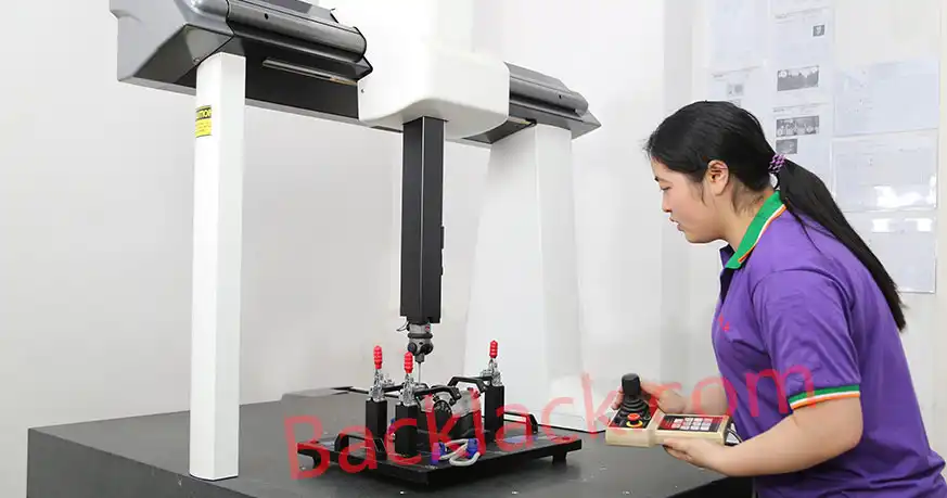
Precision Surface Grinding & CMM Metrology: Post-bonding precision back-side grinding and stepped end-tooth profiling ensure stack surface flatness within 0.02 mm. 3D CMM inspection guarantees strict slot-to-mounting-hole alignment, yielding 100% ready-to-mount linear direct-drive stators.
FAQS
Technical insights on rivet-free Backlack self-bonding technology, cogging force mitigation, ultra-thin cobalt-iron lamination stacks, and core loss optimization for high-precision linear direct-drive motors.
How does rivet-free Backlack self-bonding eliminate high-frequency losses in linear motors compared to welding or riveting?
Traditional mechanical interlocking (riveting) or laser welding seams penetrate the lamination edges, creating localized short circuits that lead to massive eddy current loops during rapid linear acceleration. Backlack self-bonding applies a 100% full-surface insulating thermosetting varnish between layers. This eliminates interlamination shorts completely, achieving near-zero eddy current spikes and maintaining up to 25% higher force density without thermal bottlenecks.
How do Backlack bonded linear motor cores help mitigate cogging forces and thrust ripples?
Unlike riveted stacks that suffer from mechanical stress deformation around rivet holes, self-bonded cores form a stress-free monolithic structure. When combined with skewed slot stamping, stepped end-tooth profiling, and precision back-side grinding, Backlack ensures smooth magnetic flux transitions. This drastically suppresses cogging forces and guarantees sub-micron tracking accuracy in precision linear motion stages.
Is Backlack bonding suitable for ultra-thin (0.10 mm) silicon steel and high-saturation Cobalt-Iron alloys?
Yes. Ultra-thin electrical steels (0.10 mm–0.15 mm) and high-saturation Cobalt-Iron alloys (such as Hiperco 50 / 1J22 with $B_{\text{sat}}$ up to 2.40 T) are extremely sensitive to mechanical stress and thermal damage. Self-bonding cures under uniform axial pressure and heat without piercing or welding the laminations, preserving 100% of the alloy's native magnetic permeability and saturation characteristics.
What stack precision tolerances can be achieved, and does Backlack support custom linear stator prototyping?
Backlack provides complete turnkey manufacturing—from custom progressive die stamping and thermosetting bonding to post-bonding precision grinding. Because linear motors operate with tight air gaps (0.5 mm to 1.0 mm), our back-side grinding and 3D CMM inspection guarantee a stack surface flatness within 0.02 mm. We offer full DFM feasibility reviews and custom prototyping for semiconductor wafer handling, medical robotics, and CNC linear stages.
Ready to Eliminate High-Frequency Thermal Bottlenecks & Eliminate Linear Direct-Drive Thrust Ripples?
Start Your Custom Self-Bonding Linear Motor Core Project Today
Conventional riveting, interlocking, and laser welding seams introduce localized interlamination short circuits, severe mechanical stress, and thermal damage, creating major performance bottlenecks in high-acceleration linear motor drives. Seeking a specialized lamination stack manufacturing partner capable of mastering ultra-thin electrical steel stamping (down to 0.10 mm), high-saturation Cobalt-Iron alloys (Hiperco® 50 / 1J22), and in-mold Backlack® self-bonding curing? Look no further! From semiconductor wafer handling stages and 5G chip inspection systems to medical robotics and precision CNC linear drives, Backlack® provides turnkey, stress-managed linear motor stator and mover solutions. By integrating precision low-burr progressive stamping, full-surface thermosetting bonding, and sub-micron back-side precision grinding (flatness within 0.02 mm), we eliminate edge shorts, suppress cogging forces, and enhance thrust density by up to 25%, seamlessly bridging the gap from rapid engineering prototypes to automated series production.
Contact our application engineering team today to request rivet-free self-bonding linear motor stator prototype sampling, receive rapid custom manufacturing quotes, or get a free Linear Lamination Stack & DFM Feasibility Evaluation for your 2D/3D CAD drawings!
Get Your Custom Quote Now