1.Executive Summary
Self-bonding motor cores are not a new idea — the technology is roughly fifty years old and has long served the most demanding machines on the planet: marine systems, aviation, rail, military aerospace, precision machine-tool spindles and high-speed motors. What has changed is that the electric-vehicle era has pushed this once-niche process into the mainstream.
Today’s EV drive motors spin at 12,000–20,000 rpm and demand power density and efficiency levels that riveted and welded stacks simply cannot deliver. The physics is unforgiving: welding leaves heat-affected zones and edge short-circuits; riveting distorts the magnetic circuit; and neither provides the joint strength, the noise performance or the compatibility with ultra-thin steel that high-speed machines require.
This article explains how self-bonding cores work, what the measurement data actually shows versus welding, why the technology is the natural partner of ultra-thin and high-silicon electrical steel, and how custom self-bonding manufacturing — the core of what we do at Backlack® — turns these advantages into production reality.
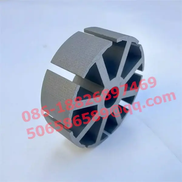
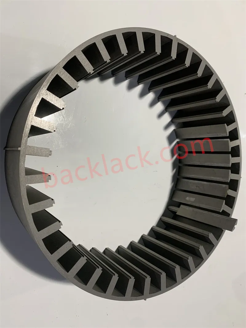
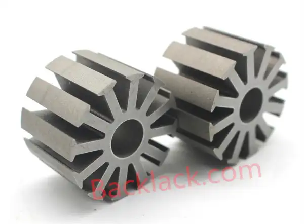
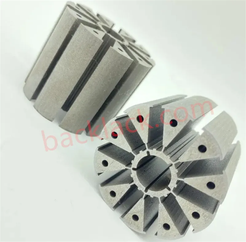
2.The speed race: why assembly now decides motor performance
Two trends are rewriting the rules for motor cores:
In this regime, the way laminations are joined stops being a manufacturing detail and becomes a first-order design variable. A poor joint can undo the gains of an excellent material — and this is exactly where riveting and welding fall short.
3.Why riveting and welding are hitting their limits
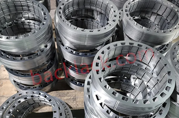
Conventional stator and rotor stacks are held together three ways — riveting, welding, or mechanical interlocking. Each carries hidden costs that grow with speed and frequency:
- Welding creates a large heat-affected zone. The thermal damage degrades insulation, can cause edge short-circuits between laminations, and the rough weld seam is both an appearance and a performance defect — not to mention the environmental and energy cost of the process.
- Riveting physically deforms the lamination, narrowing the magnetic path and damaging the very magnetic structure the core exists to provide. The deformation is local but the magnetic cost is global.
- Both are local fixings. Rivets and welds hold only discrete points. The connection force is limited, and at 12,000–20,000 rpm the centrifugal and vibrational loads on a rotor core far exceed what point-fixings were ever designed to carry.
Drive motors already run at 12,000 rpm, with 20,000 rpm architectures in development. A stack that relies on a few rivets or weld points will micro-move, fatigue, and lose dimensional stability — long before the magnets or bearings are anywhere near their limits. The joint, not the material, becomes the weakest link.
4.How self-bonding cores work
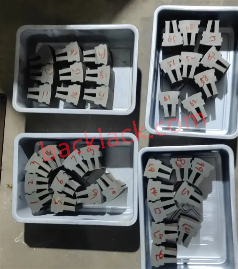
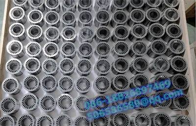
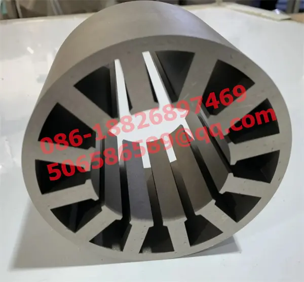
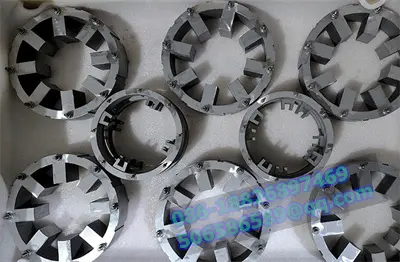
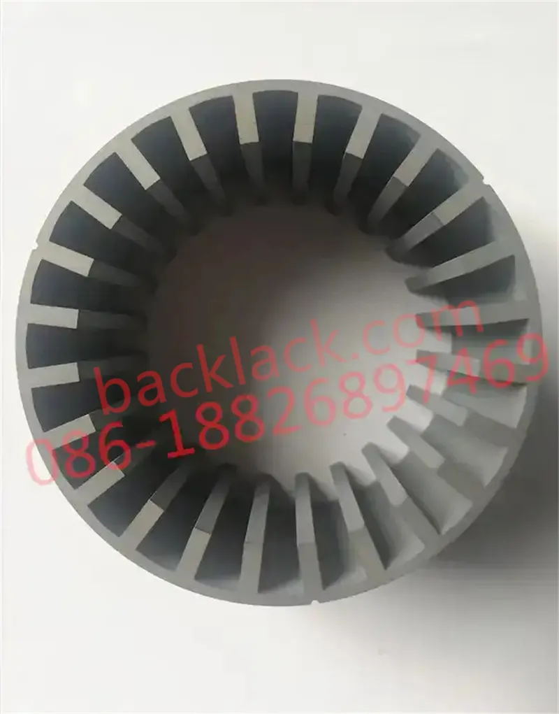
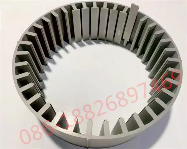
The principle is elegant because it lives inside the steel coating itself. A self-bonding electrical steel carries an adhesive-containing coating that is completely non-tacky at room temperature — so the material handles, stacks and ships exactly like a normal coated steel. The bond only happens when you want it to:
- Laminations are stacked to the target stack height.
- Pressure and heat are applied under controlled conditions.
- The adhesive melts, flows, fills the microscopic gaps between laminations, and cures.
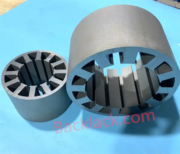
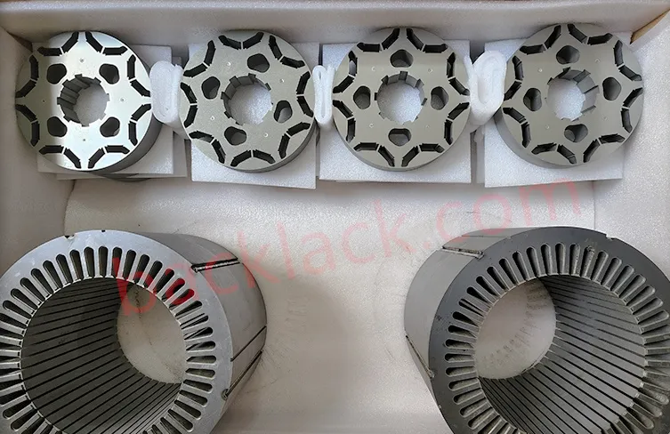
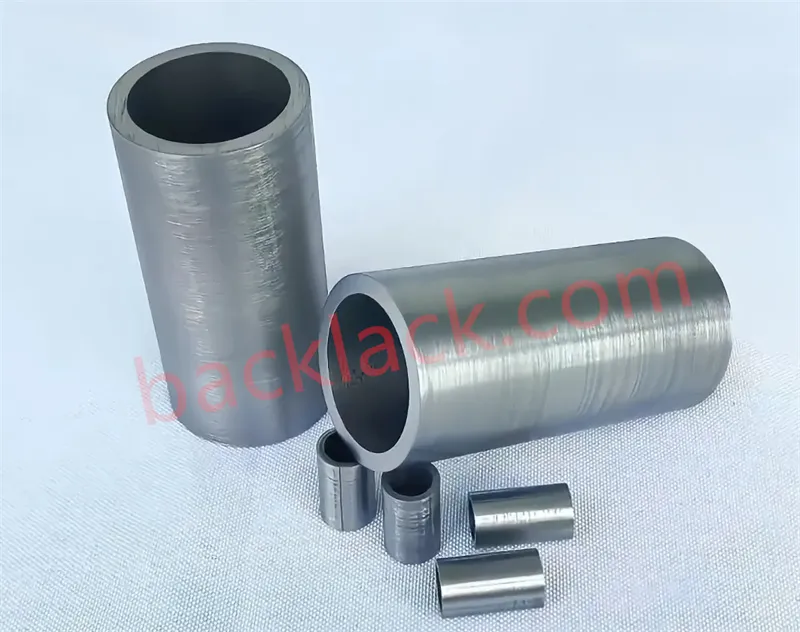
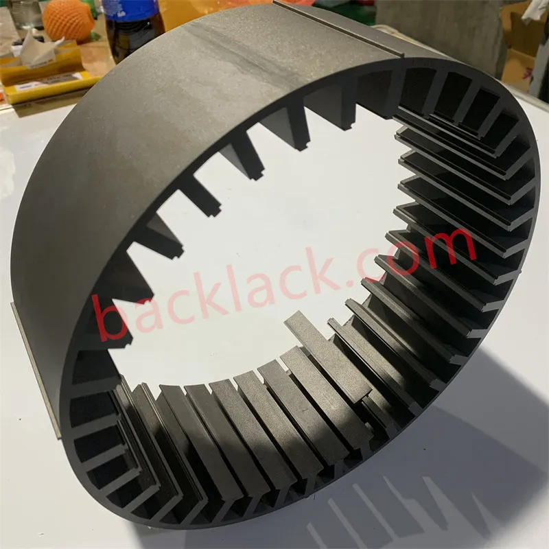
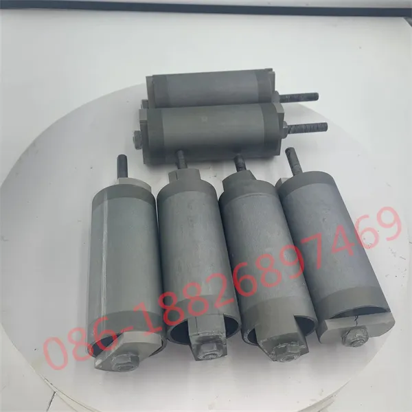
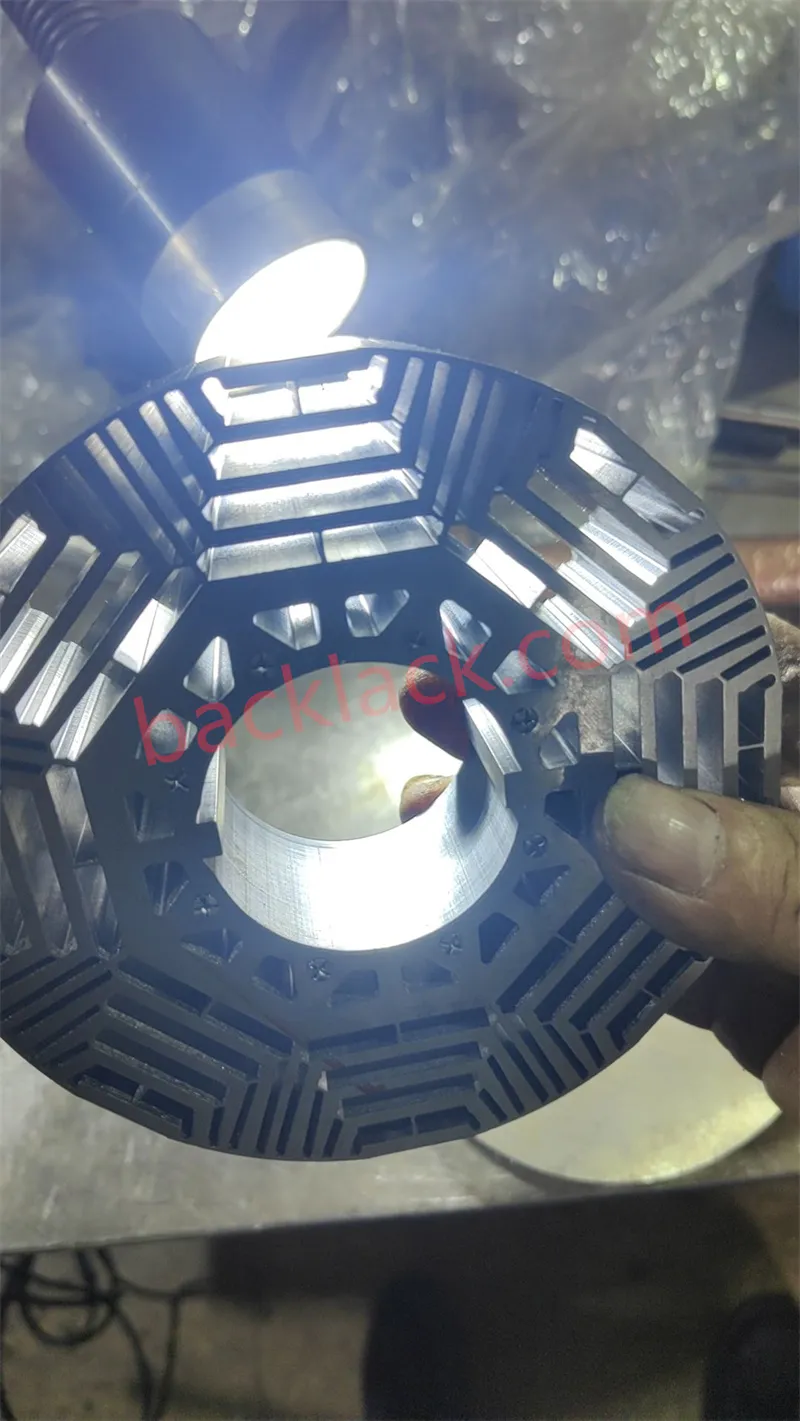
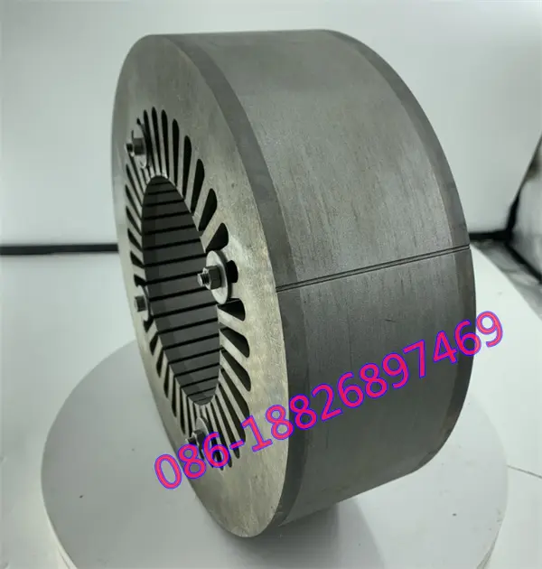
- The result is a single rigid monolith — no rivets, no welds, no fasteners.
Because the adhesive wets the full surface area of every lamination, the joint is continuous rather than point-like. That changes the mechanical, magnetic, acoustic and thermal behaviour of the core all at once.
5.What the data shows: self-bonding vs welding
Comparative tests of bonded versus welded cores (magnetic induction 1.5 T, 50 Hz, identical test conditions) consistently show the same picture:
| Measurement | Self-bonding core vs welded core | Engineering meaning |
|---|---|---|
| Core loss | −5% | Less heat in the iron path — directly protects efficiency and reduces thermal load |
| Exciting current | −9% | Easier magnetisation, lower drive burden |
| Noise (same induction) | −5 dB | Roughly 45% less acoustic energy from the core itself |
| Axial vibration (excited state) | Nearly zero vs. measurable for welded | The monolithic bond damps magnetostrictive and harmonic excitation |
| Radial vibration | Same result as axial | Consistent NVH benefit in all directions |
Compared with riveting, the bonded core is also more stable in service: the full-area bond suppresses micro-movement between laminations, reduces eddy-current paths created by mechanical damage, and removes the need for end plates, pressure rings and fasteners — freeing axial space for a longer effective core in the same motor length.
6.The ultra-thin connection: material & process
Iron loss falls when laminations get thinner — that is why cores are never solid blocks. The ideal is the thinnest steel that still assembles reliably. But here is the paradox: ultra-thin steel is exactly the material that riveting cannot handle and welding cannot touch.
- Riveting ultra-thin steel is practically impossible — there is simply not enough material to form a reliable mechanical joint without destroying the lamination.
- Laser welding ultra-thin steel creates local electrical conduction between layers — precisely the short-circuit path that thin laminations exist to prevent.
Self-bonding solves the assembly problem without adding any magnetic penalty. The adhesive does not conduct, does not deform, and does not create a heat-affected zone. This is why bonding is the natural companion of high-performance thin-gauge materials such as 0.10 mm high-silicon electrical steel.
The material and the process are, in fact, validated together. JFE Steel’s own demonstration of a 0.10 mm 10JNEX900 motor core uses room-temperature punching with bonding as the lamination-fixing method — and their motor evaluation (a 4-pole IPM machine, φ105 mm stator, 45 mm stack) shows efficiency above 5,000 rpm improved by roughly 2 percentage points versus a high-grade conventional non-oriented steel.
Ultra-thin steel removes the loss that frequency creates; the bonded stack removes the loss, noise and structural risk that the assembly would otherwise add. Thin steel riveted still suffers edge shorts and stack chatter. Bonded thick steel still cannot fix harmonic losses. You need both — and that combination is exactly what a self-bonding core delivers.
7.What self-bonding removes: longer cores, higher power density
Beyond losses and noise, bonded cores change the mechanical layout of the motor. Because no rivets, pressure rings, end plates or fasteners are needed to hold the stack together, the space they would have occupied can be used for active magnetic material instead:
- Longer effective stack length in the same package — directly raising torque and power density.
- Fewer parts in the BOM and assembly line — simpler logistics, fewer tolerance chains.
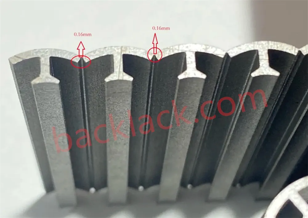
- Cleaner, more precise stacks — tight stack-height and parallelism control with no mechanical deformation.
- Design freedom — shapes and tooth geometries that riveting or interlocking could not hold together can now be produced and fixed reliably.
8.Where self-bonding cores are already the standard
The technology has migrated from extreme applications to the mainstream, and the list of adopters reads like a roadmap of the electric economy:
Defence & aerospace
military aerospace, submarines and special vehicles — where vibration, noise and reliability are non-negotiable.
Air mobility
electric aircraft and UAV/drone propulsion systems.
Ground transport
EV drive motors, high-speed rail and maglev traction.
Marine
electric vessels and recreational electric boats.
Power conversion
high-efficiency generators, motors and transformers.
New energy systems
robotics, hydrogen fuel-cell vehicles and flywheel energy storage.
Across all of these, the same design drivers apply: higher speed, higher power density, lower noise and longer life — exactly the properties a self-bonding core provides.
9.Custom self-bonding cores from Backlack®
We manufacture precision motor cores with exactly the combination this technology needs — thin and high-silicon electrical steels joined by full-area bonding. Our service covers the full chain:
- Material selection. We help you choose the right grade for your speed and frequency profile — from ultra-thin 0.10 mm high-silicon steel (e.g. 10JNEX900) to conventional thin-gauge grades — with loss data to justify the choice.
- Die design & stamping. Precision progressive dies and low-burr stamping developed for thin, brittle, high-silicon material.
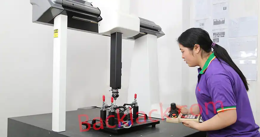
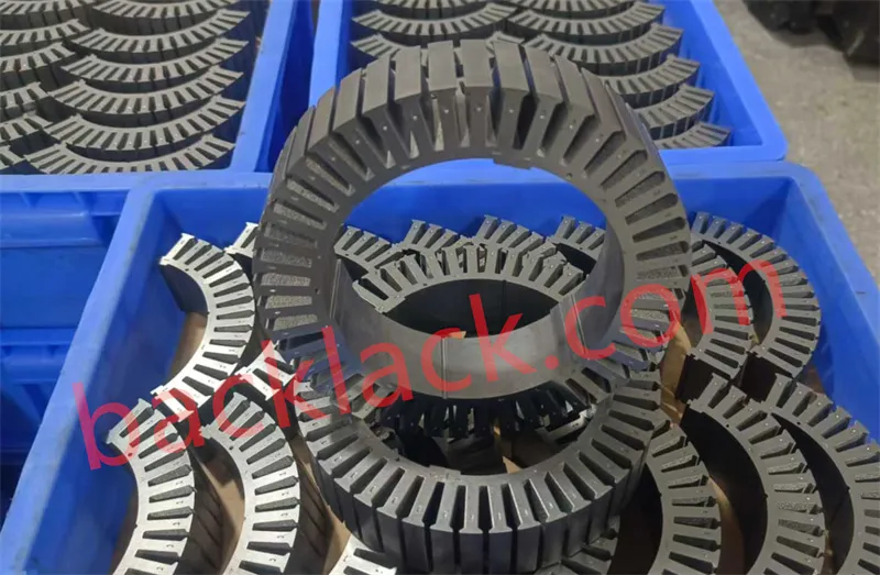
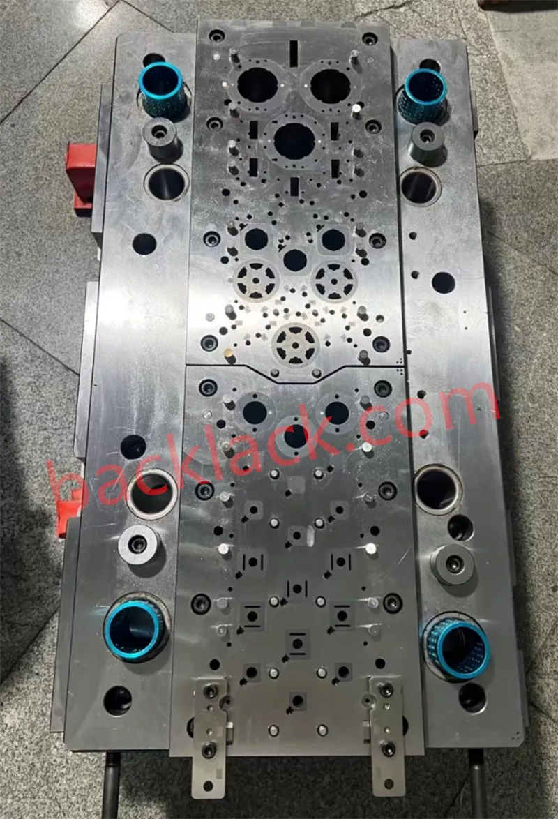
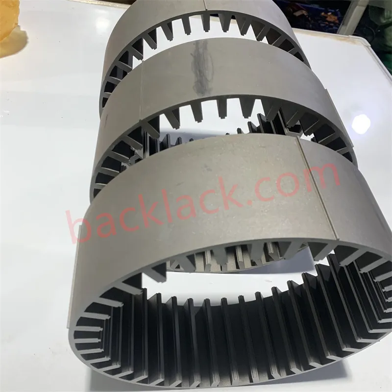
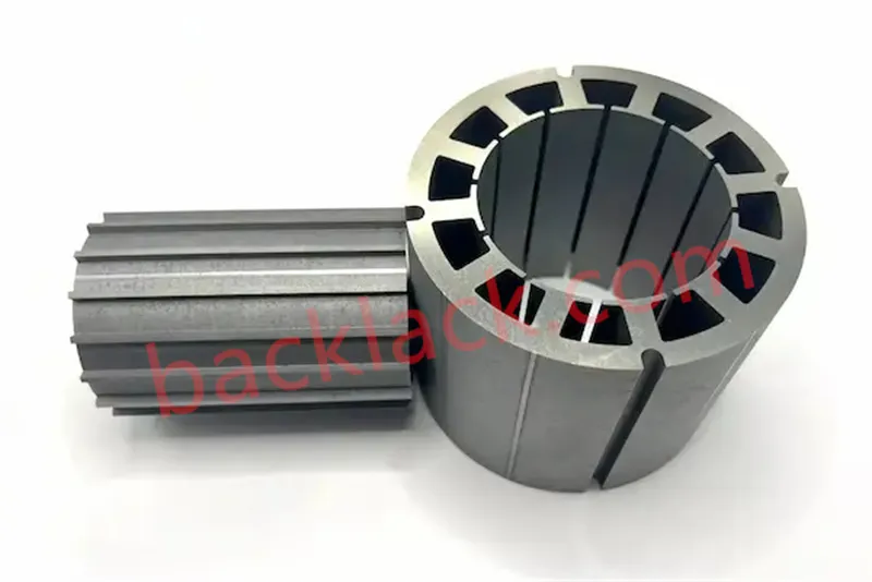
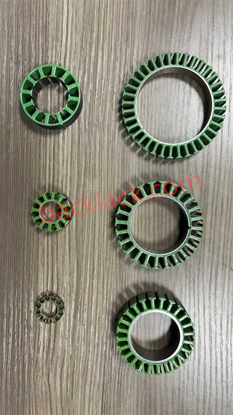
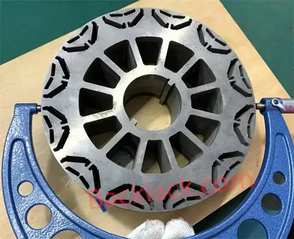
- Self-bonding assembly. Full-area adhesive bonding under controlled pressure and temperature, fusing laminations into rigid, dimensionally precise rotor and stator stacks.
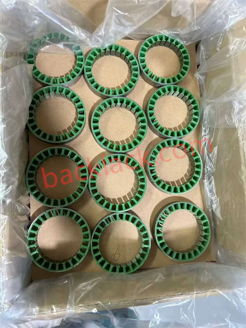
- Inspection & delivery. Stack height, parallelism and geometry verified before shipping — ready-to-wind or ready-to-assemble cores per your BOM.
About Backlack®
Traditional assembly methods like riveting and welding disrupt the magnetic circuit structure and induce severe thermal damage or edge short-circuits, creating a major bottleneck in high-speed, high-efficiency drive motor manufacturing. As a specialized motor core precision manufacturer, Backlack® overcomes the critical industry bottleneck of joining ultra-thin and high-silicon electrical steel laminations. By integrating precision low-burr progressive die stamping, full-area thermo-press adhesive curing, and tight stack parallelism control, we eliminate interlamination short circuits, reduce core loss (-5%), decrease exciting current (-9%), and damp noise (-5 dB). We provide turnkey, single-source precision manufacturing from electrical steel coils to ready-to-wind rotor and stator stacks for EV drive motors, electric aerospace propulsion, medical robotics, and high-performance electromagnetic systems.
Ready to eliminate interlamination loss and resolve high-speed motor core assembly bottlenecks?
Contact our engineering team today to request self-bonding stator and rotor prototype sampling or get a complete Material Selection & Lamination Bonding DFM Evaluation for your motor drawings!