Executive Summary
Executive Summary: As electric propulsion systems demand extreme torque density, ultra-high operating frequencies (>1,000 Hz), and stringent thermal dissipation, traditional continuous-ring stator laminations hit rigid physical and economic boundaries. This technical whitepaper evaluates how segmented stator architecture—integrated with sub-micron progressive stamping and zero-stress Backlack self-bonding technology—overcomes winding slot limitations, drastically lowers high-frequency core loss, and minimizes silicon steel waste for global Tier-1 OEMs.1. The Physics Bottleneck of Continuous-Ring Stators in High-Frequency Applications
In conventional brushless DC (BLDC), permanent magnet synchronous motors (PMSM), and traction motors, the continuous-ring stator design forces winding needles to navigate through narrow slot openings. This creates three critical engineering limitations:
Slot Fill Restriction (I2R Copper Loss Spike)
Internal needle winding in closed or semi-closed slots restricts the slot fill factor to roughly 55%–65%. Restricted conductor volume directly elevates phase resistance, causing excessive copper losses (I2R) and overheating at peak current.
End-Turn Overhang & Over-Weighting
Manual or needle winding on continuous stators produces tall, un-utilized copper end-turns, adding dead weight without generating torque.
Raw Material Cost Inefficiency
Stamping full-circle stator rings out of electrical steel coils leaves huge inner-bore and slot scrap, dropping material utilization rates to a prohibitive 45%–55%.
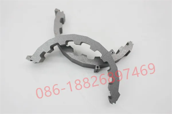
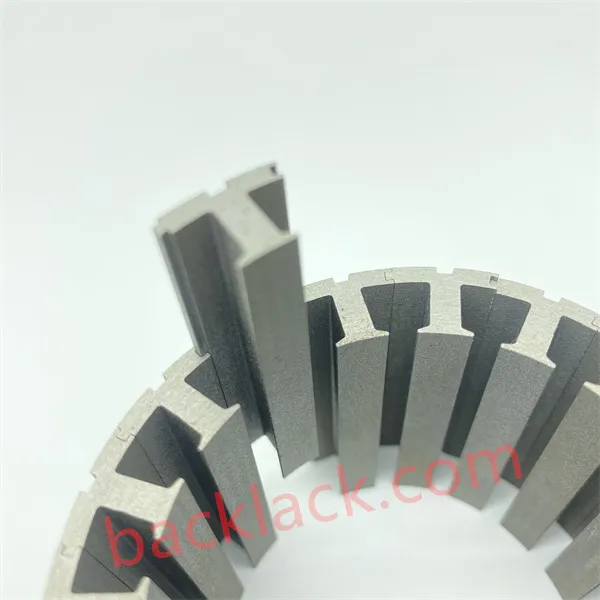
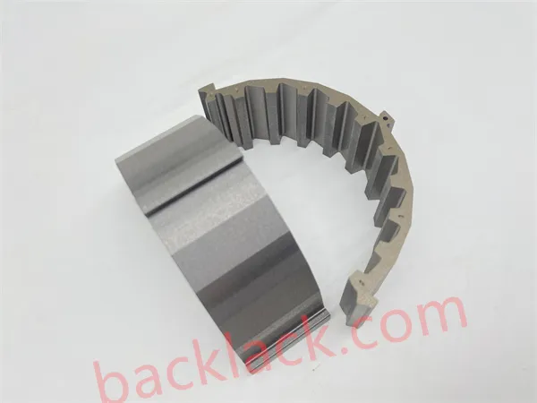
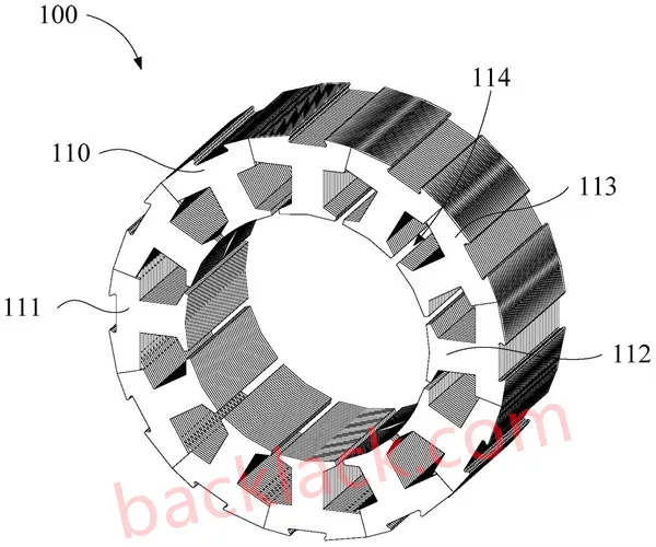
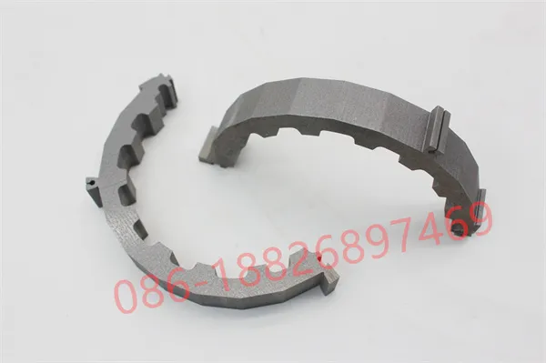
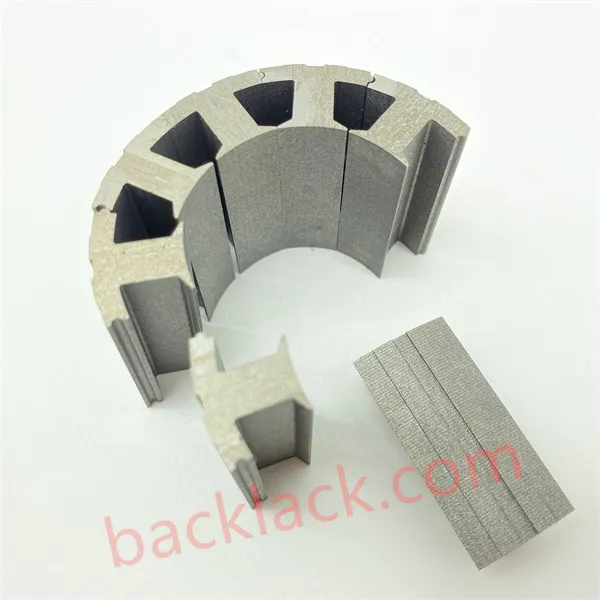
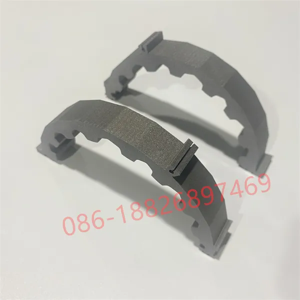
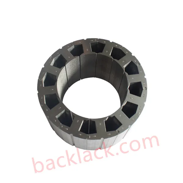
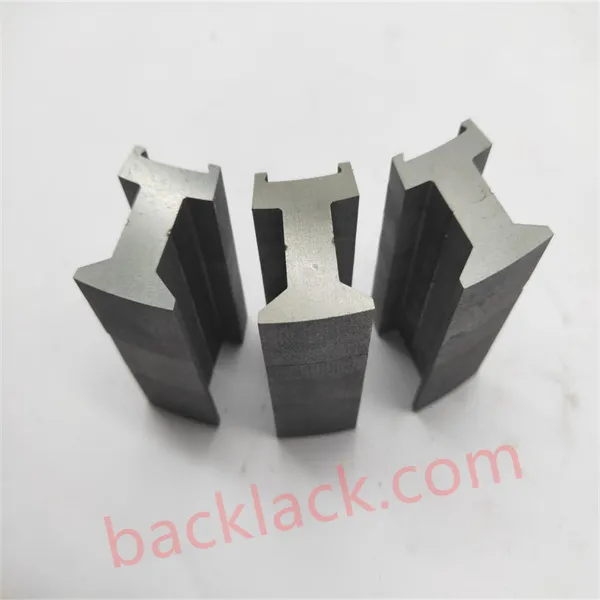
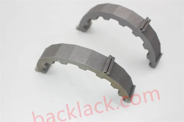
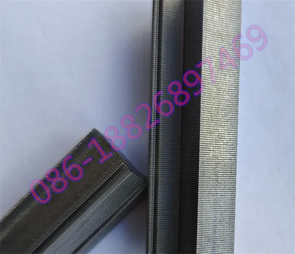
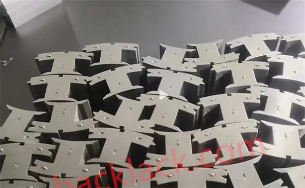
2. Architectural Overhaul: Concentrated Direct Tooth Winding & Modular Topologies
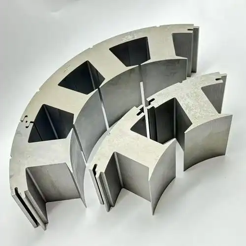
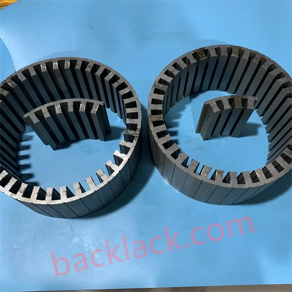
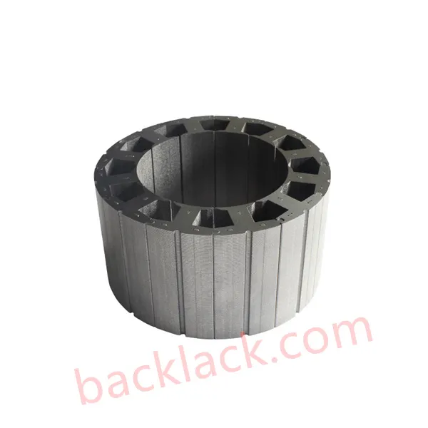
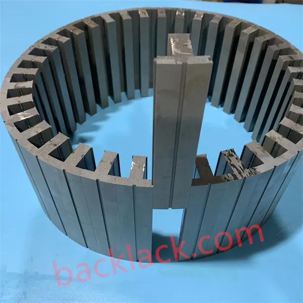
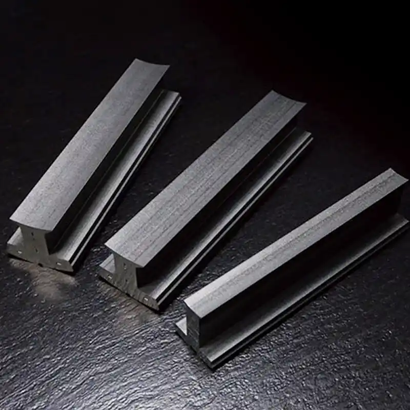
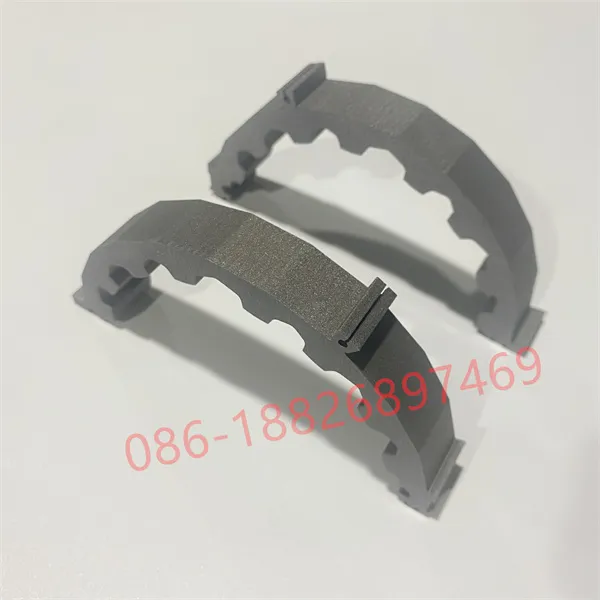
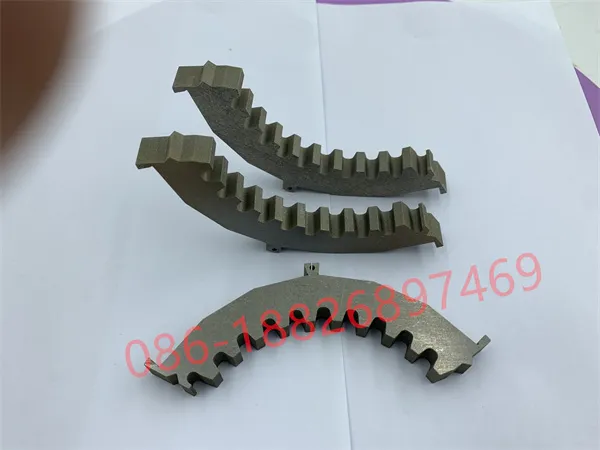
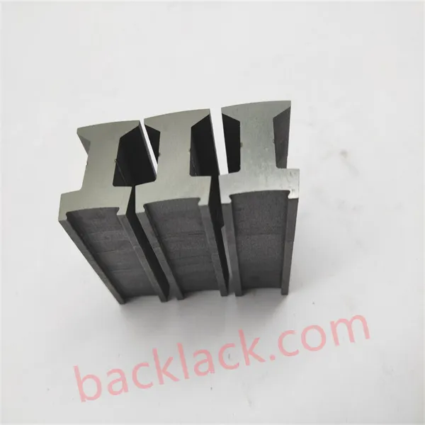
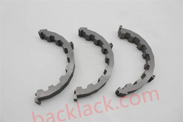
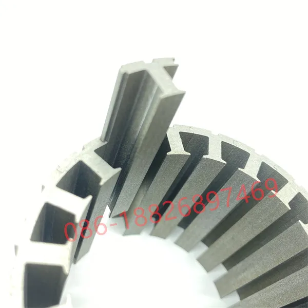
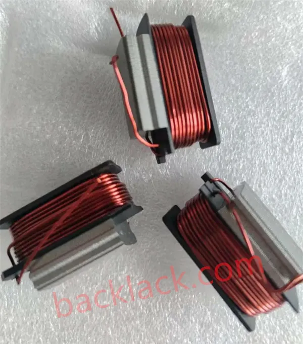
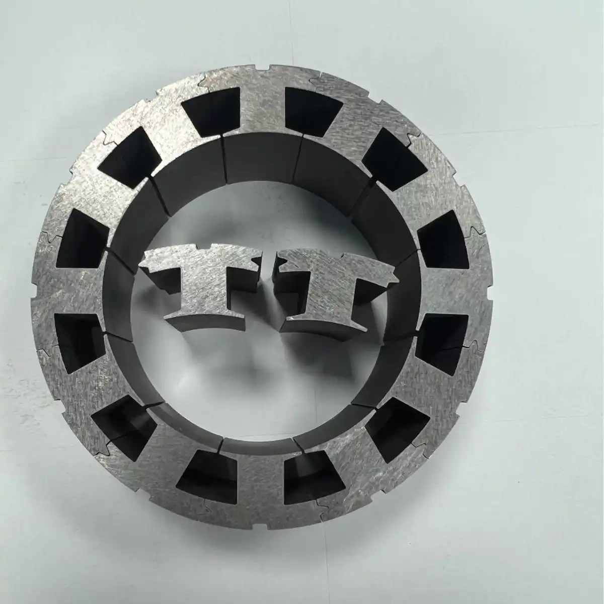
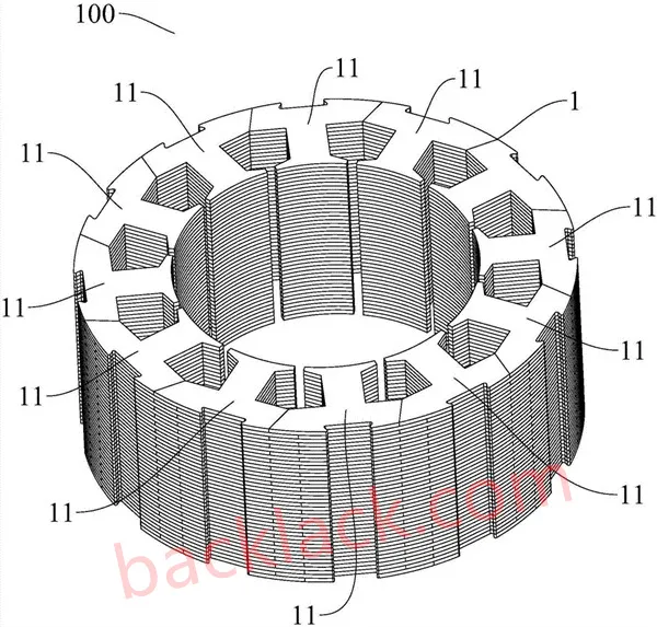
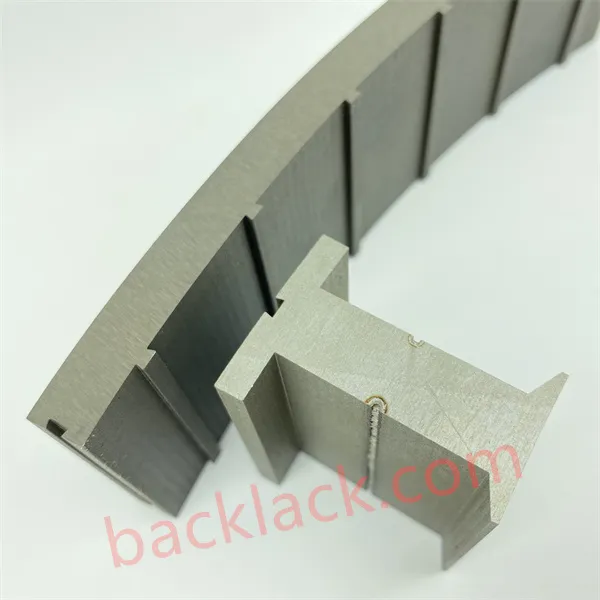
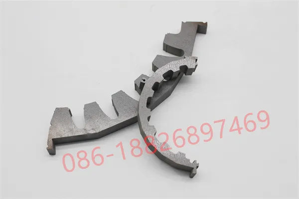
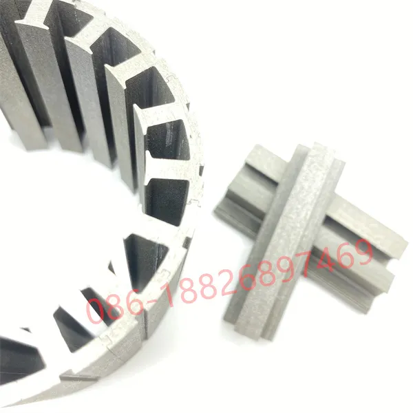
Segmenting the stator into individual T-shaped tooth laminations transforms motor assembly from an internal restriction puzzle into an unconstrained external manufacturing process.
A. Direct Tooth Winding (Concentrated Winding)
By extracting each tooth segment individually, automated CNC winding fliers operate externally with zero spatial constraint. This enables:
- Increasing the slot fill factor from 60% up to 78%–82%+ using precision linear winding or rectangular flat wire.
- Minimizing end-turn wire length, reducing total copper mass by up to 18%, and significantly cutting phase resistance.
- Extending insulation paper lifespan due to zero mechanical abrasion during external bobbin/tooth winding.
B. Material Optimization for High-Grade Electrical Steels
For high-frequency motors requiring 0.1mm to 0.2mm ultrathin electrical steel laminations or Cobalt-Iron (CoFe) soft magnetic alloys, raw material accounts for over 65% of total stack cost. Modular tooth nesting on progressive dies reduces punching scrap dramatically, boosting silicon steel material utilization to 85%–90% and optimizing overall BOM expenditure.
3. Resolving the Parasitic Air Gap & Stress Issues via Backlack Self-Bonding
Historically, motor designers avoided segmented stators due to two major technical risks: parasitic air gaps at segment joint interfaces and core loss spikes caused by laser welding or interlocking rivets.
Youyou Company eliminates these drawbacks through the synergy of sub-micron carbide tooling and Backlack (Self-Bonding Coating) Technology.
| Key Engineering Metric | Standard One-Piece Stator | Segmented (Laser Welded / Riveted) | Youyou Company Backlack Segmented Stator |
|---|---|---|---|
| Joint Tolerance & Gap | N/A (Continuous Ring) | 0.015 mm - 0.030 mm (High Reluctance) | ≤ ±0.008 mm (Negligible Reluctance) |
| Interlaminar Short Circuit | Low (Punching Stress Only) | High (Welding seams short-circuit sheets) | Zero (Pure Epoxide Insulation Barrier) |
| High-Frequency Core Loss (W/kg) | Baseline Reference | +20% to +35% Loss Increase | -12% Loss Reduction vs. Welded Stacks |
| Structural Shear Strength | High | Localized Stress Concentration | > 20 MPa Full Surface Adhesion |
| Acoustic Noise / NVH Damping | Moderate | Poor (Loose segment vibration) | Superior (Polymer Matrix Damps Harmonics) |
Technical Breakthrough: How Backlack Eliminates Joint Short Circuits
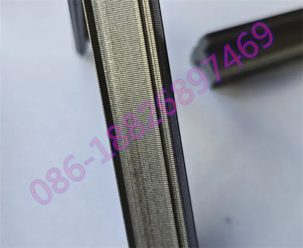
Traditional laser welding across lamination edges creates conductive bridges that break sheet-to-sheet insulation, generating massive eddy current loops at high frequencies (>400 Hz). Our pre-coated B-stage epoxy silicon steel is stamped, assembled, and cured under precise thermal-compression cycles. The fully cross-linked polymer binds 100% of the lamination surface area without introducing mechanical stress, maintaining the raw material's pristine hysteresis loop.
4. Precision Manufacturing & Quality Control Protocol
To deliver flawless segmented stator lamination stacks for aerospace, automotive, and medical applications, Youyou Company enforces an end-to-end quality framework:
5. DFM Prototyping & Mass Production Capabilities for Global OEMs
As an IATF 16949 certified motor core manufacturer, Youyou Company provides comprehensive Design for Manufacturability (DFM) support for international procurement and technical engineering teams:
- Rapid Prototyping (7–10 Business Days): Wire-EDM / High-precision laser cutting combined with custom curing fixtures for rapid functional testing before tooling sign-off.
- Scalable Mass Production: High-speed progressive stamping presses (100T–300T) delivering millions of precision stator segments annually with full CMM and Epstein frame testing traceability.
- Global Supply Chain Alignment: RoHS, REACH, and ISO 9001 compliant with complete material certification (Epstein core loss curves, tensile test data, and coating thickness reports).
Optimize High-Frequency Motor Performance with Backlack Segmented Stator Architecture
Submit your 3D CAD models or drawings for a comprehensive Segmented Tooth DFM Feasibility Assessment, Backlack thermal-bonding analysis, or rapid prototyping (7–10 days lead time).
Quality Control for Segmented Stator Cores & Backlack Laminations
As a specialized precision motor lamination manufacturer, Youyou Company enforces full-process quality control for Segmented Stator Architectures and Backlack Self-Bonding Stacks. Combining sub-micron progressive stamping (0.1mm–0.2mm ultrathin silicon steel), zero-stress thermal-compression bonding, and sub-micron joint clearance testing, we deliver high-slot-fill, ultra-low loss stator segments engineered for high-frequency electric propulsion, aerospace actuators, and high-rpm motors.
Raw Material Verification & Coating Integrity: 100% material certificate verification and lot traceability on high-grade electrical steels (0.1mm–0.2mm ultrathin silicon steel and soft magnetic alloys). We strictly inspect gauge uniformity, insulation coating resistance, and B-H loss curves prior to progressive stamping.
Sub-Micron Punching & Micro-Burr Height Control: Custom carbide progressive dies maintain segment tooth pitch tolerances within ±0.005 mm. Strict micro-burr control (<0.005 mm) prevents interlaminar short circuits and guarantees seamless assembly of individual tooth segments.
Backlack Thermal Bonding & Zero Mechanical Stress: Temperature- and pressure-controlled curing process eliminates the need for rivet interlocking or edge welding. This full-surface epoxide bonding preserves original magnetic permeability, eliminates weld-induced eddy currents, and maximizes shear strength (>20 MPa).
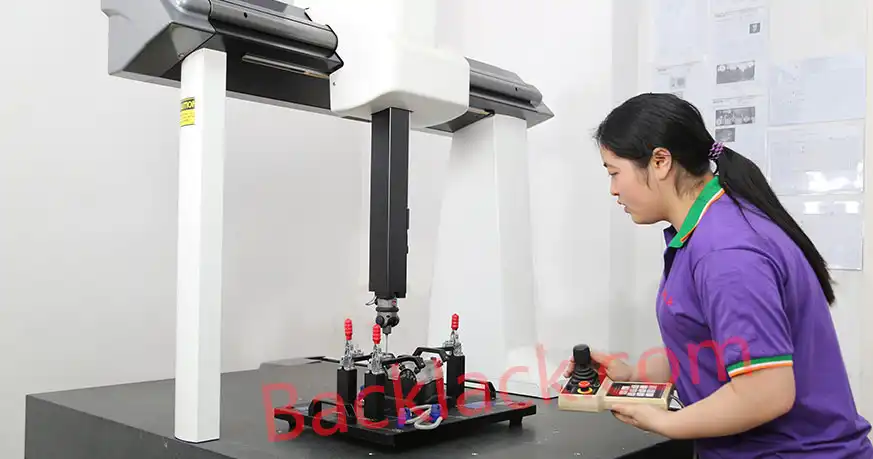
Joint Gap Metrology & Stator Core Testing: Optical coordinate measuring machines (CMM) ensure joint interface gaps stay below 0.008 mm, minimizing parasitic magnetic reluctance. 100% core loss (W/kg) testing ensures strict compliance with OEM high-frequency efficiency specifications.
FAQS
Technical insights on Segmented Stator Architectures, Backlack self-bonding technology, ultrathin silicon steel laminations (0.1mm–0.2mm), direct tooth winding, and high-frequency core loss reduction.
What are the key electromagnetic advantages of Segmented Stators over continuous-ring stators?
Segmented stator architectures eliminate winding space constraints by allowing individual teeth to be wound externally. This boosts the slot fill factor from ~60% up to 78%–82%+, drastically reducing copper resistance (I2R loss). Additionally, segmented nesting on electrical steel coils increases raw material utilization to 85%–90% (compared to ~50% for traditional one-piece ring stators).
Why is Backlack (Self-Bonding Coating) critical for segmented stator tooth stacks?
Traditional laser welding or interlocking rivets create conductive bridges across lamination edges, causing severe interlaminar short circuits and eddy current spikes at high frequencies (>400 Hz). Backlack technology uses full-surface B-stage epoxy bonding that cures without mechanical stress. This maintains zero interlamination shorts, reduces core loss by 12% compared to welded stacks, and provides high shear strength (>20 MPa).
How does Youyou Company eliminate parasitic air gaps at the segment joint interfaces?
Parasitic air gaps at segment joints increase magnetic reluctance and lower motor torque. Youyou Company utilizes sub-micron precision progressive carbide tooling to control tooth wedge tolerances within ±0.005 mm and micro-burr heights under 5 microns. This guarantees seamless interlocking with assembly joint gaps ≤ 0.008 mm, rendering parasitic reluctance virtually negligible.
Which silicon steel grades and gauges are recommended for high-rpm segmented stators?
For ultra-high frequency and high-rpm motors, we process ultrathin non-oriented silicon steel laminations ranging from 0.10 mm to 0.20 mm, as well as grain-oriented grades and high-performance Cobalt-Iron (CoFe) alloys (such as Vacodur 49 / 1J22). Thin gauges dramatically lower high-frequency hysteresis and eddy current losses in compact electric propulsion and medical robotics motors.
What support does Youyou Company offer for prototype development vs. mass production?
We provide full-lifecycle DFM engineering support for global OEMs. For rapid R&D prototyping, we deliver custom wire-EDM or laser-cut Backlack segment samples in 7–10 business days. For serial production, our high-speed progressive stamping presses (100T–300T) deliver millions of bonded tooth segments annually under strict IATF 16949 quality protocols.
Ready to Eliminate High-Frequency Core Losses & Overcome Electric Motor Thermal Bottlenecks?
Start Your Custom Segmented Stator & Backlack Core Project Today
Conventional one-piece ring stators encounter rigid physical limits—restricting slot fill factors to ~60%, generating excessive copper (I2R) losses, and wasting up to 50% of costly electrical steel. Looking for an experienced motor core manufacturer capable of processing ultrathin silicon steel (0.10mm–0.20mm) and high-performance alloys alongside advanced Backlack self-bonding technology? Youyou Company delivers turnkey, low-loss stator solutions for high-speed electric propulsion, drone motors, medical robotics, and aerospace actuators. By integrating sub-micron carbide stamping, direct tooth winding optimization, and stress-free Backlack thermal curing, we eliminate interlaminar short circuits, boost slot fill factors up to 82%, and elevate material utilization to 90%, seamlessly bridging the gap from rapid engineering prototyping to automated series production.
Contact our application engineering team today to request Backlack self-bonding lamination samples, get rapid turn-around on prototypes (7–10 days), or receive a free Segmented Stator DFM Feasibility Evaluation for your 3D CAD models and drawings!
Get Your Custom Quote Now