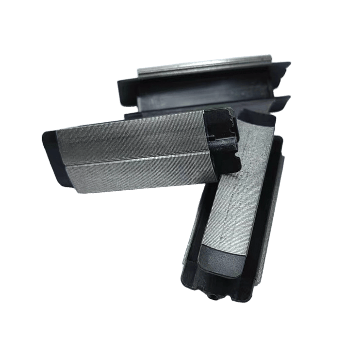
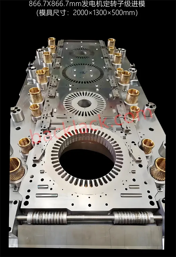
Overview of progressive die for motor stator and rotor core
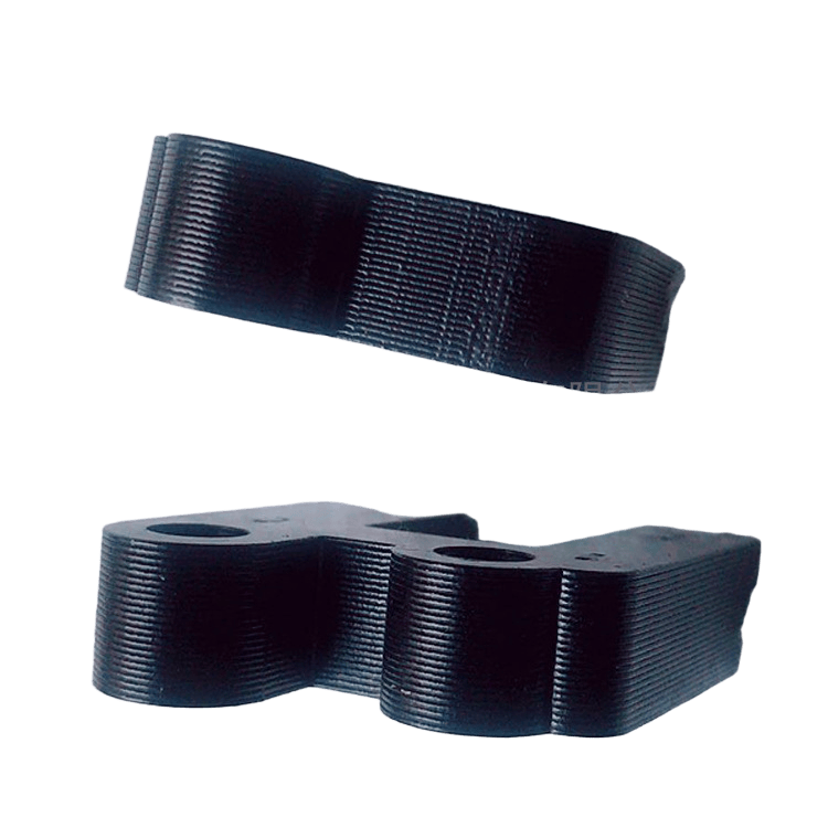
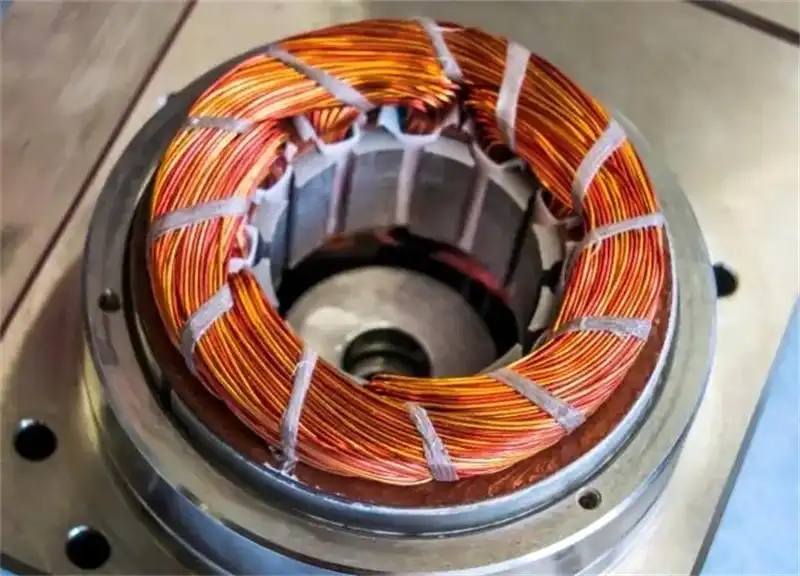
In the motor industry, stator and rotor cores are one of the important parts of the motor, and their quality directly affects the technical performance of the motor. The traditional method of making cores is to use ordinary dies to punch out stator and rotor punchings (loose sheets), align the sheets, and then use rivets, buckles or argon arc welding to make the core. For AC motor rotor cores, it is also necessary to twist the inclined grooves manually. Stepper motors require that the magnetic properties and thickness directions of the stator and rotor cores are uniform, and the stator core and rotor core punchings are required to rotate a certain angle respectively. If the traditional method is used, the efficiency is low and the accuracy is difficult to meet the technical requirements. Now with the rapid development of high-speed stamping technology, high-speed stamping multi-station progressive dies have been widely used in the fields of motors, electrical appliances, etc. to manufacture automatic laminated structural cores. Among them, the stator and rotor cores can also have twisted stacking skew grooves, and large-angle rotary stacking riveting structures between the punching sheets. Compared with ordinary punching dies, multi-station progressive dies have the advantages of high punching accuracy, high production efficiency, long service life, good consistency of dimensional accuracy of the punched cores, easy automation, and suitable for mass production. It is the development direction of precision molds in the motor industry. The stator and rotor automatic stacking riveting progressive dies have high manufacturing accuracy, advanced structure, and high technical requirements. Rotary mechanism, counting separation mechanism and safety mechanism, etc. The punching steps of automatic stacking riveting of iron cores, rotor with twisted stacking riveting, and large-angle rotary stacking riveting are all completed at the stator and rotor punching blanking station. The main parts of the progressive die, the punch and the die, are made of carbide materials. Each time the cutting edge is ground, it can punch more than 1.5 million times, and the total life of the die is more than 120 million times.
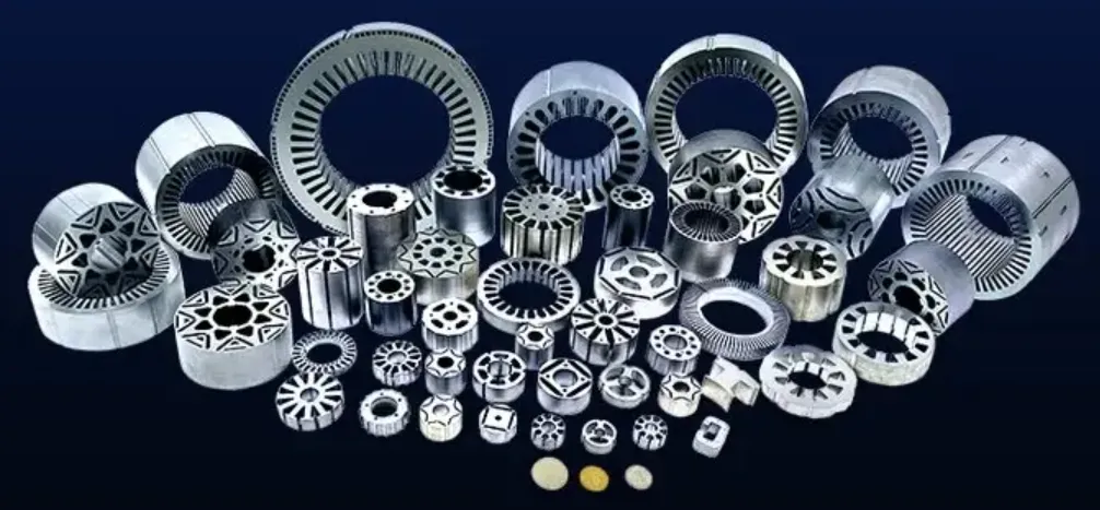
Automatic riveting technology for motor stator and rotor cores
The automatic riveting technology on the progressive die is to complete the original traditional process of making cores (punching out scattered pieces - aligning pieces - riveting) in a die, that is, adding new stamping technology on the basis of the progressive die. In addition to the requirements for the shape of the punching pieces such as the shaft holes and slot holes on the stator and rotor, the riveting points required for the stator and rotor cores and the counting holes for the separation of the riveting points are added. The original stator and rotor blanking stations are changed to riveting stations that first play the blanking role, and then make each punching piece form the riveting process and the stacking counting separation process (to ensure the thickness of the core). If the stator and rotor cores need to have twisting and rotating riveting functions, the lower die of the progressive die rotor or stator blanking station should be equipped with a twisting mechanism or a rotating mechanism, and the riveting points on the punching piece are constantly changing or rotating to achieve this function, thereby meeting the technical requirements of automatically completing the riveting and rotating riveting of the punching piece in a die.
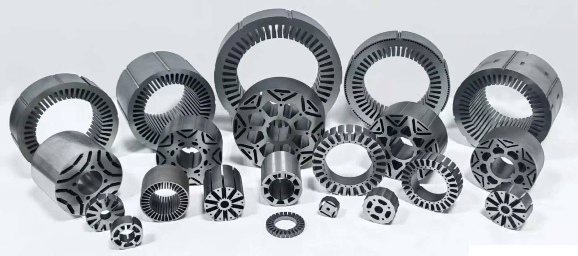
The process of automatic lamination of the core
The process of automatic lamination of the core is to punch out a certain geometric shape of rivet points on the appropriate parts of the stator and rotor punching sheets. The form of the rivet points is shown in Figure below.
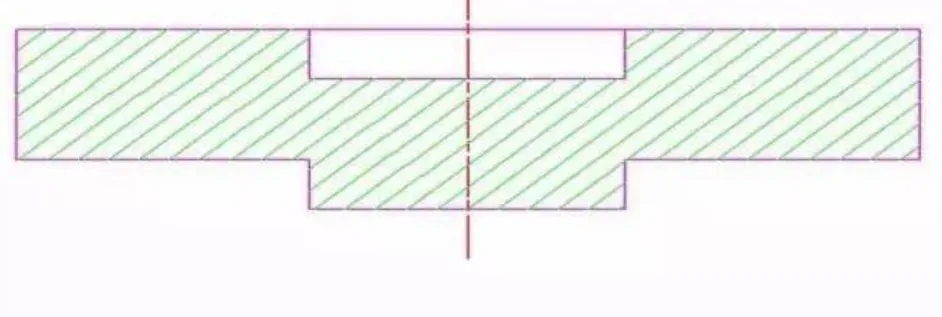
The upper part is a concave hole and the lower part is convex. Then, when the convex part of the upper punching sheet of the same nominal size is embedded in the concave hole of the next punching sheet, an "interference" is naturally formed in the tightening circle of the blanking die in the mold to achieve the purpose of fastening connection.
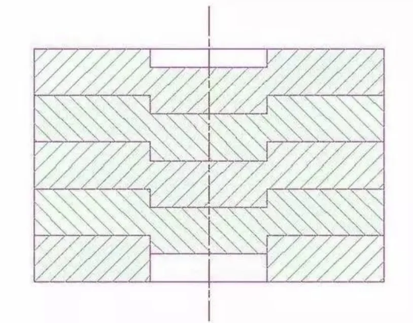
As shown in Figure above. The process of forming the core in the mold is to make the convex part of the rivet point of the upper sheet correctly overlap with the concave hole part of the rivet point of the lower sheet at the blanking station of the punching sheet. When the upper sheet is subjected to the pressure of the blanking punch, the lower sheet uses the reaction force generated by the friction between its outer shape and the wall of the die to cause the two sheets to rivet. In this way, through continuous punching by a high-speed automatic punching machine, a neat core with one sheet next to another, burrs in the same direction and a certain stacking thickness can be obtained.
The control method of the thickness of the core lamination is as follows:
When the number of core sheets is predetermined, punch through the stacking rivet point on the last punching sheet, so that the core is separated according to the predetermined number of sheets, as shown in Figure below.
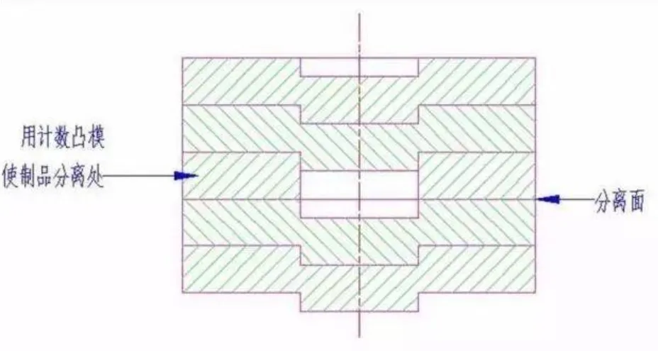
An automatic stacking counting and separation device is provided on the mold structure
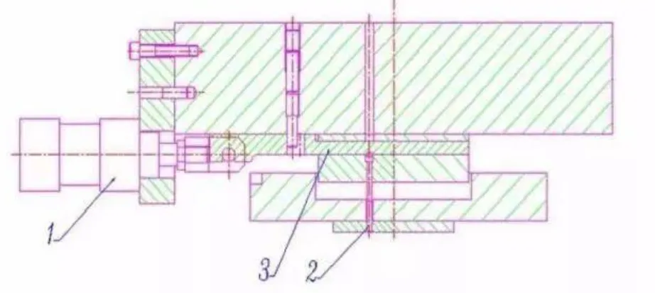
As shown in Figure above. There is a plate extraction mechanism on the counting punch, which is driven by a cylinder, and the cylinder movement is controlled by a solenoid valve, which moves according to the instructions issued by the control box. Each stroke signal of the punch is input into the control box. When the set number of sheets is punched, the control box will send a signal to make the plate extraction move through the solenoid valve and the cylinder, so that the counting punch can achieve the purpose of counting and separation, that is, the metering hole is punched through and the metering hole is not punched at the stacking rivet point of the punching sheet. The thickness of the core lamination can be set by yourself. In addition, the shaft hole of some rotor cores is required to be punched into 2 or 3 sections of shoulder countersunk holes due to the needs of the supporting structure.
As shown in Figure above, the progressive die needs to simultaneously punch the core with the shoulder hole process requirements. The above-mentioned similar structural principle can be used.
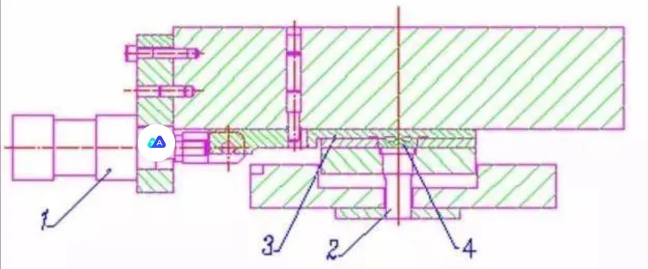
The above-mentioned similar structural principle can be used, and the mold structure is shown in Figure above.
There are two types of core stacking structures
The first is the close stacking type, that is, the stacked riveted core does not need to be pressurized outside the mold, and the core stacking strength can be achieved after the mold is removed. The second is the semi-closed stacking type. There is a gap between the stacked riveted core punching sheets when the mold is removed, and further pressure is required to ensure the bonding strength.
Setting and determination of the number of core stacking rivets
The selection of the core stacking rivet point position should be determined according to the geometric shape of the punching sheet. At the same time, considering the electromagnetic performance and use requirements of the motor, the mold should consider whether there is interference between the punch and die insert positions of the stacking rivet point and the strength of the distance between the stacking rivet ejector pin hole position of the blanking punch and the edge. The distribution of the rivet points on the core should be symmetrical and uniform. The number and size of the rivet points should be determined according to the required bonding force between the core punching sheets, and the manufacturing process of the mold must be taken into account. If there are large-angle rotation rivets between the core punching sheets, the equal division requirements of the rivet points should also be considered. As shown in Figure below.

The geometric shapes of the core rivet points are

Cylindrical rivet points
which are suitable for the close-stacked structure of the core;

V-shaped rivet points
which are characterized by high connection strength between the core punching sheets and are suitable for the close-stacked structure and semi-close-stacked structure of the core;

L-shaped rivet points
which are generally used for the twisted rivet of the rotor core of the AC motor and are suitable for the close-stacked structure of the core;

Trapezoidal rivet points
which have round trapezoidal and long trapezoidal rivet point structures, both of which are suitable for the close-stacked structure of the core.
Interference of the rivet point
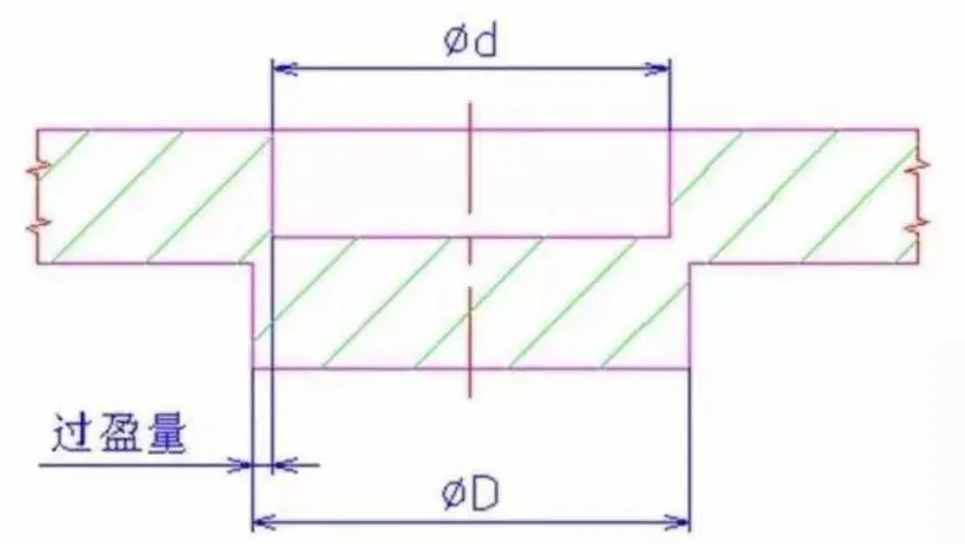
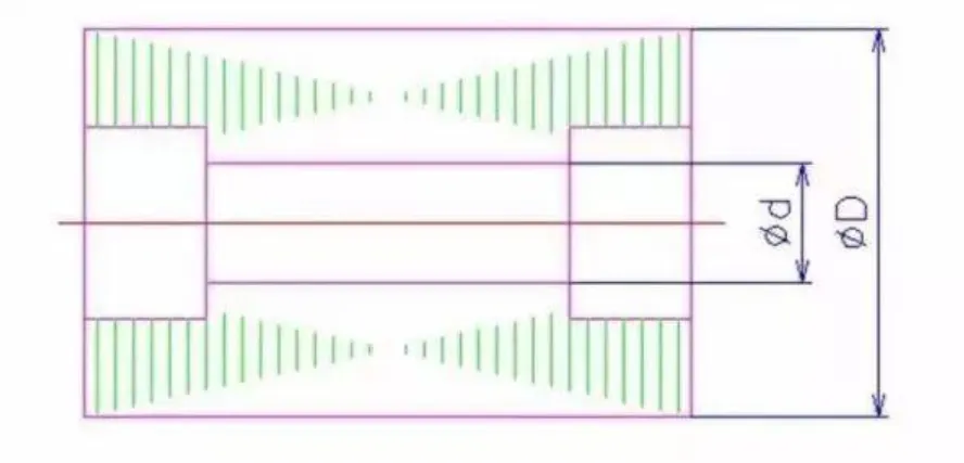
The strength of the core rivet is related to the interference of the rivet point. As shown in Figure below, the size difference between the outer diameter D and the inner diameter d of the rivet point boss (i.e., the interference) is determined by the edge clearance between the punch and the die of the rivet point. Therefore, selecting the appropriate clearance is an important part of ensuring the strength of the core rivet and the difficulty of the rivet.
